

Valve life testing device
A life test and valve technology, applied in the field of machinery, to achieve the effect of small footprint, simple structure, accurate and effective testing
Inactive Publication Date: 2010-08-18
ZHEJIANG WORLD BRASS
View PDF5 Cites 22 Cited by
- Summary
- Abstract
- Description
- Claims
- Application Information
AI Technical Summary
Problems solved by technology
At present, the more common gate valves and globe valves on the market rely on the threaded transmission of the screw or the valve core to drive the movement of the seal to achieve the opening and closing function. The life of this valve is largely determined by the screw or the valve core. Whether it can be sealed at the end, the life test for this type of valve is equivalent to the life test for the screw valve core, but there is no testing equipment for this type of screw valve core in the market
Method used
View moreImage
Smart ImageViewing Examples

Examples
Embodiment 2
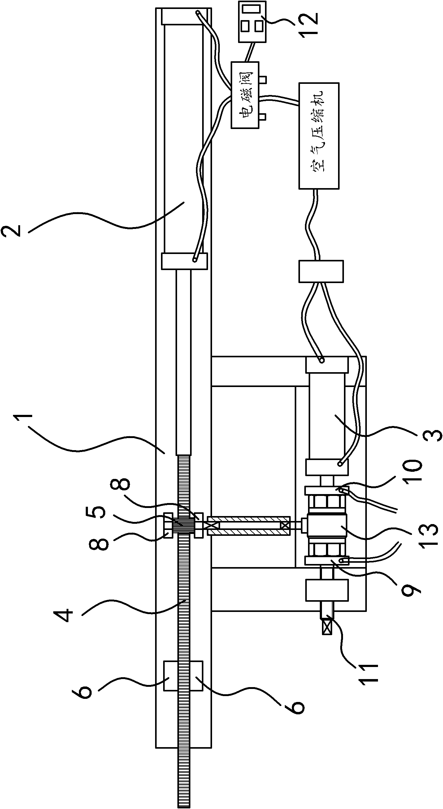
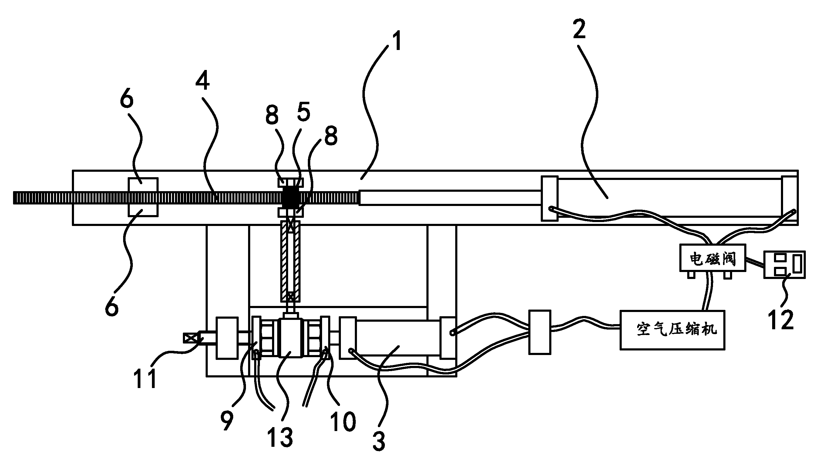
[0029] The structure and principle of this embodiment are basically the same as that of Embodiment 1, the difference is that the control mechanism includes a solenoid valve connected to the air pipe of cylinder 1 2 and a touch switch arranged on cylinder 1 2, the solenoid valve and the touch switch The switches are all connected with the PLC.
Login to View More PUM
 Abstract
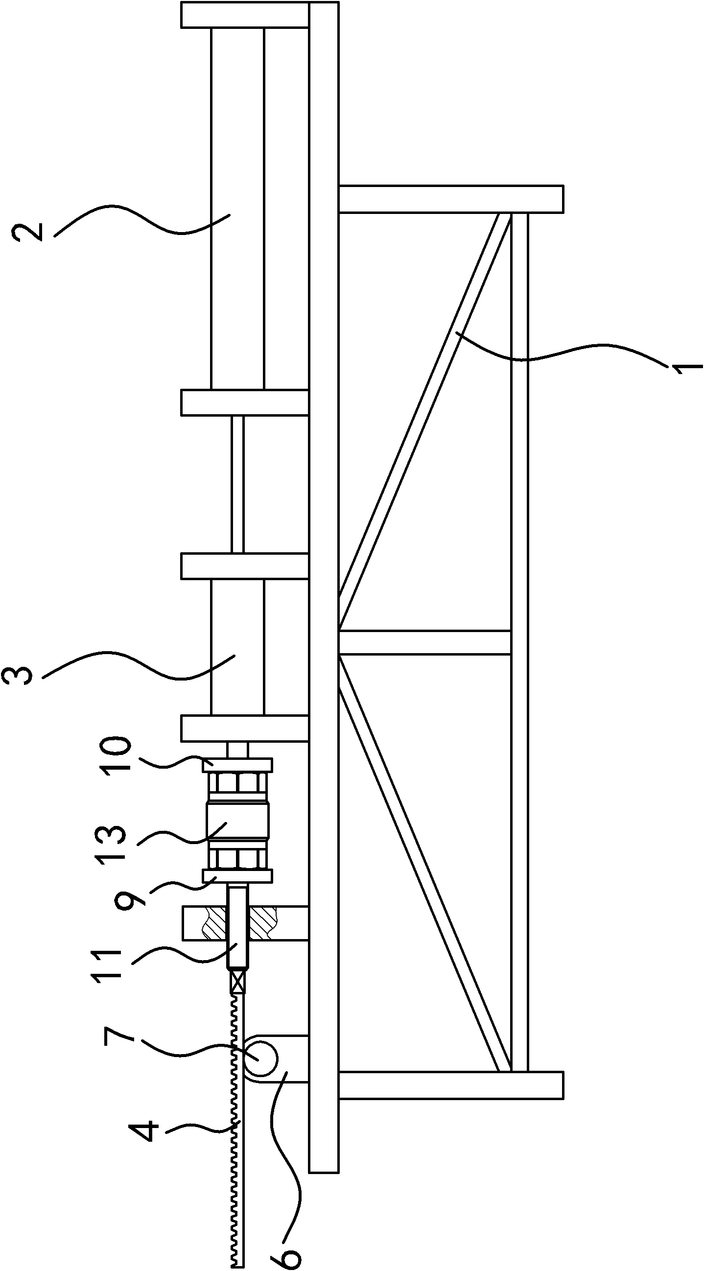
The invention provides a valve life testing device which belongs to the technical field of machinery and solves the problem that no testing equipment for a lead screw valve core exists on a traditional market. The valve life testing device comprises a stand, wherein the stand is provided with a clamping mechanism which can fix the valve body of a valve on the stand, the stand is provided with a cylinder 1 and a rotating sleeve which can be connected with the lead screw of the valve, a rack is connected to the piston rod of the cylinder 1, and the rotating sleeve is connected with a gear engaged with the rack; when the piston rod of the cylinder 1 extends and shrinks, the rotating sleeve can rotate; and the cylinder 1 is connected with a control mechanism which can control the sliding stroke of the piston rod. The valve life testing device has the advantages of simple structure, convenient use, capability of on-line pressurized testing, small occupied area and accurate and effective testing.
Description
technical field [0001] The invention belongs to the technical field of machinery, in particular to a valve life testing device. Background technique [0002] There are more and more types of existing valves. According to their different designs and operating principles, their testing equipment and methods also need to be adjusted in time. At present, the more common gate valves and globe valves on the market rely on the threaded transmission of the screw or the valve core to drive the movement of the seal to achieve the opening and closing function. The life of this valve is largely determined by the screw or the valve core. Finally, it can be determined whether it can be sealed. The life test for this type of valve is equivalent to the life test for the screw valve core, but there is no testing equipment for this type of screw valve core on the market. Contents of the invention [0003] The object of the present invention is to solve the above-mentioned problems in the e...
Claims
Login to View More Application Information
Patent Timeline
 IPC IPC(8): G01M19/00G01M99/00
Inventor卓旦春
OwnerZHEJIANG WORLD BRASS