
Ion implanter system with beam decelerator

An ion implanter and beam reducer technology, which is applied to discharge tubes, electrical components, circuits, etc., can solve the problems of ion beam energy pollution, inability to generate uniform low energy, and obvious end effect of the deflection reduction device, and achieve reduction The effect of little end effect

Inactive Publication Date: 2010-08-18
胡新平 +1
View PDF5 Cites 11 Cited by
  • Summary
  • Abstract
  • Description
  • Claims
  • Application Information

AI Technical Summary

Problems solved by technology

[0010] In order to solve the problems in the prior art, the present invention provides an ion implanter system with a beam decelerator, which solves the obvious end effect of the deflection deceleration device in the current ion implantation system, which cannot produce uniform low-energy ion beams and produces The problem of large energy pollution

Method used


Image

  • Ion implanter system with beam decelerator
  • Ion implanter system with beam decelerator
  • Ion implanter system with beam decelerator

Examples


Embodiment Construction

[0037] First, some explanations about the existing technology:

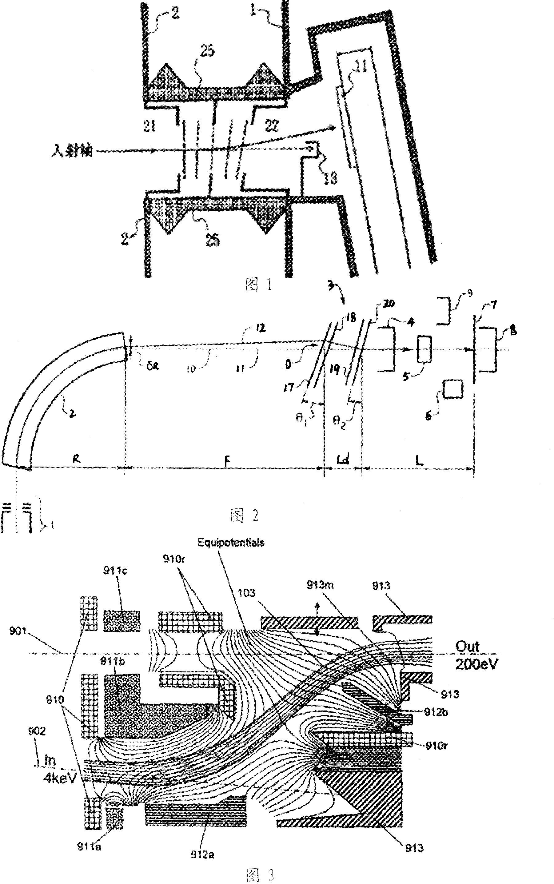
[0038] figure 1 Reprinted from Japanese Patent No. 4-284343, showing the use of inclined electrodes as deflection reducer devices. The inclined electrode decelerates and deflects the ion beam at the same time. Therefore, the ion beam is decelerated, and the deflection separates the neutral atoms or molecules from the ion beam from the upstream. This type of reduction gear is generally called a deflection reduction gear.

[0039] figure 2 Reprinted from US Patent No. 6,441,382, it shows the use of inclined electrodes as a curve reducer device; the electrode device combined with the upstream mass analysis magnet changes the orbit direction of the ion beam many times. The electrode device decelerates and deflects the ion beam at the same time. Therefore, the ion beam is decelerated, and the deflection separates the upstream neutral atoms or molecules from the ion beam. This type of reduction gear is generally called a...


PUM


Abstract

The invention relates to the filed of implantation of ion beams, and discloses an ion implanter system with a beam decelerator. The ion implanter system comprises an ion beam system and a target chamber system, wherein the ion beam system comprises an ion source generating ion beams and an electromagnetic device used for selecting, forming and transmitting the ion beams to a target chamber; and the target chamber system is used for scanning a target workpiece. The ion implanter system is characterized in that: the ion implanter system also comprises a deceleration device which is positioned at an upstream position of the target chamber system, reduces the energy of the ion beams and removes harmful upstream neutral molecules and atoms; and the deceleration device comprises a series of electrode pairs which are provided with side electrodes. The ion implanter system has the advantages of eliminating energy pollution of the ion beams and reducing the end effect of the electrodes by decelerating and deflecting the ion beams through multiple electrodes.

Description

Technical field [0001] The invention relates to the field of ion beam implantation, in particular to an ion implanter system with a beam reducer. Background technique [0002] Ion implantation is a process of introducing atoms or molecules into the target workpiece substrate. This process is usually called doping, which can change the properties of the material. Ion implantation is a common process in the manufacture of large-scale integrated circuits. Ion implantation can also be used in thin film deposition and other manufacturing processes related to the manufacture of optical instruments or display instruments (such as flat panel displays). A typical ion implanter includes an ion source that generates an ion beam; an ion beam selection, shaping, and delivery system that includes an ion beam quality analysis system that uses a magnetic field; and a target chamber for processing semiconductors that will be injected into the ion beam Silicon wafer. For low-energy implantation ...

Claims


Application Information

Patent Timeline
IPC IPC(8): H01J37/317H01J37/05
Inventor 胡新平黄永章
Owner 胡新平
Learn More