
Hygiene cleaning device

A cleaning device and hygienic technology, which is applied to water supply devices, sanitary equipment for toilets, buildings, etc., can solve the problems of narrow nozzles, increased flow rate, and difficult cleaning of nozzles, and can ensure the uniformity of expansion, maintenance of cleanliness, The effect of preventing adhesion

Active Publication Date: 2012-05-16
PANASONIC CORP
View PDF1 Cites 0 Cited by
  • Summary
  • Abstract
  • Description
  • Claims
  • Application Information

AI Technical Summary

Problems solved by technology

In order to spread the spray flow from the gap at the front end of the toilet nozzle in the same manner, there is a problem that if the gap of the flow path is 0.3mm, if the deviation of the gap of the flow path is not limited to a width range of at least ±0.05mm The inner jet spreads unevenly
Then there is the problem as follows: the jet stream that spreads thinly in the same way as to reach the toilet surface, the flow velocity is accelerated to more than 4m, and the jet stream itself becomes a film, so there is a jet stream that is easy to become splashed, especially when the jet stream is sprayed out. When the flow of the jet flow is disturbed at the outlet, the jet flow becomes very easy to splash when it reaches the surface of the toilet, and the splashed water bubbles disperse and reach the toilet seat or the outside of the toilet
[0009] In addition, since the discharge port is very narrow, there is a problem that dirt and scale adhere to the discharge port, the discharge direction of the jet flow changes, or clogging occurs in extreme cases. In addition, there are also problems when cleaning the discharge port. In some cases, there is still room for improvement from the viewpoint of ensuring sufficient cleanliness due to the problem that it is difficult to clean because the nozzle is very narrow.

Method used


Image

  • Hygiene cleaning device
  • Hygiene cleaning device
  • Hygiene cleaning device

Examples


Embodiment approach 1

[0052] Appearance of sanitary cleaning device and toilet device equipped with it

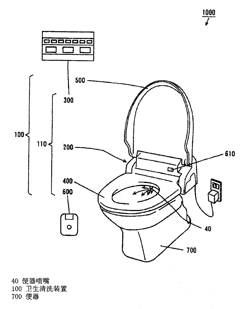
[0053] figure 1 It is a perspective view which shows the external appearance of the sanitary washing apparatus and the toilet apparatus equipped with it in Embodiment 1 of this invention. The toilet device 1000 is installed in the toilet.

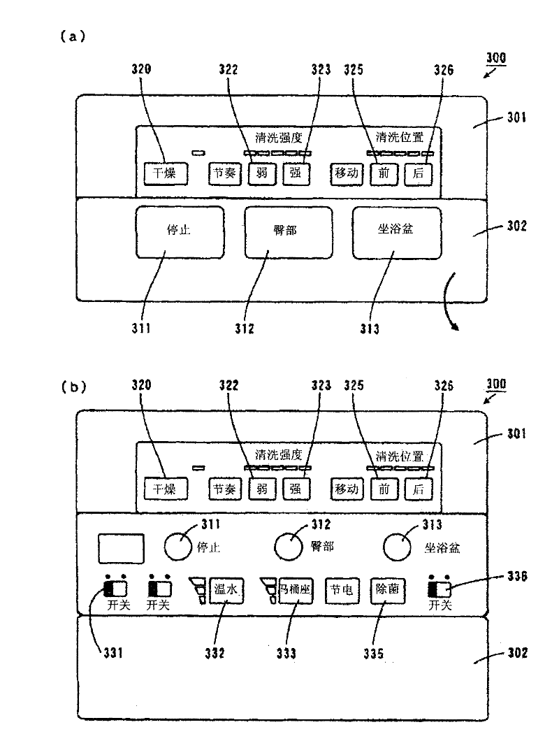
[0054] In toilet device 1000 , sanitary cleaning device 100 is attached to toilet 700 . The sanitary cleaning device 100 is composed of a main body 200 , a remote control device 300 , a toilet seat 400 and a cover 500 . Each component of the sanitary washing device 100 excluding the cover part 500 constitutes the toilet seat device 110 described later.

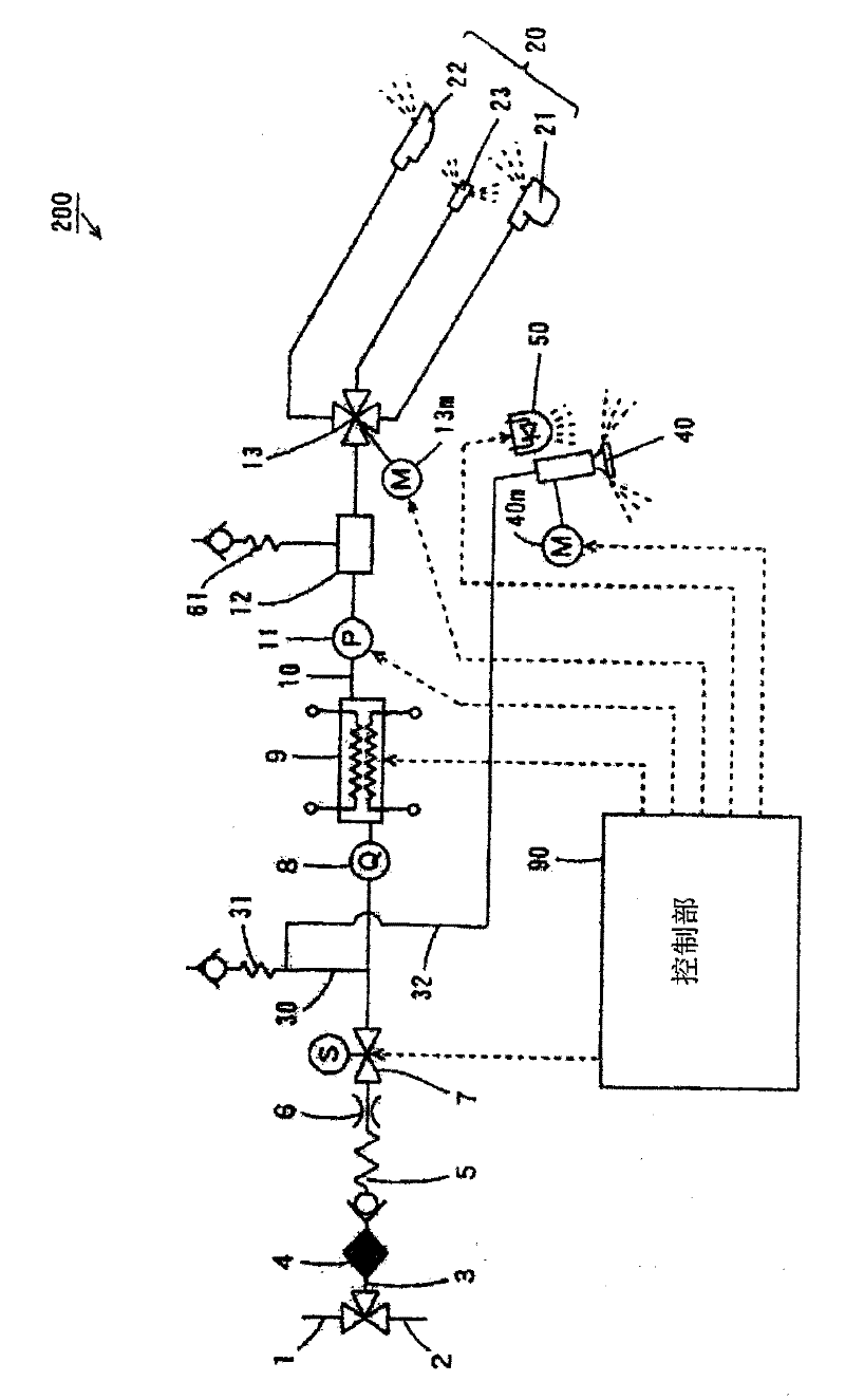
[0055] A toilet seat 400 and a lid 500 are attached to the main body 200 so as to be openable and closable. In addition, a washing water supply mechanism (not shown) is provided on the main body 200, and a control unit 90 ( image 3 ).

[0056] exist figure 1 In , the seating sensor 610 provided on th...


PUM


Abstract

A hygiene cleaning device that prevents cleaning water from splashing on a human body and sufficiently prevents human wastes from adhering to a toilet bowl. The hygiene cleaning device (100) has a toilet bowl nozzle (40). The toilet bowl nozzle (40) has a toilet bowl nozzle body (41) and a jet flow forming member (42) inserted in the toilet bowl nozzle body (41). A gap is provided between the toilet bowl nozzle body (41) and the jet flow forming member (42) so that the jet flow forming member (42) is freely movable in the toilet bowl nozzle body (41). If the gap functioning as a flow path forthe cleaning water were non-uniformly formed,the distribution of pressure in the flow path would be non-uniform to cause a jet flow ejected from the toilet bowl nozzle (40) to be a deviated flow. However, because the jet flow forming member (42) is freely movably installed, the pressure of the cleaning water acts in the direction in which the gap becomes uniform. As a result, the position of the jet flow forming member (42) is automatically corrected to make the jet flow from the toilet bowl nozzle (44) uniform.

Description

technical field [0001] The invention relates to a sanitary cleaning device with a toilet nozzle for cleaning a toilet. Background technique [0002] Conventionally, in order to prevent dirt from adhering to the toilet, various sanitary cleaning devices have been developed (for example, refer to Patent Document 1). [0003] In the sanitary cleansing device described in Patent Document 1, when a person sits on the toilet seat, cleansing water is sprayed from the toilet nozzle toward the inner surface of the toilet. Therefore, the inner surface of the toilet is wetted with the washing water to form a water film on the surface of the toilet, thereby preventing dirt from adhering to the toilet. [0004] Patent Document 1: Japanese Patent Application Laid-Open No. 7-189319 [0005] In the sanitary cleaning device described in Patent Document 1, the toilet nozzle is provided with a cover body at the front end of the toilet nozzle body, and a predetermined gap is formed between th...

Claims


Application Information

Patent Timeline
Patent Type & Authority Patents(China)
IPC IPC(8): E03D9/08
CPCE03D9/002
Inventor 古闲良一
Owner PANASONIC CORP
Learn More