Prepuce peritomy anastomoses device

A circumcision and stapler technology, applied in the field of medical devices, can solve problems such as affecting the recovery of the circumcision, pain during the circumcision, leaving scars, etc.

Active Publication Date: 2010-08-25
WUHU SHANGRING TECH CO LTD
View PDF1 Cites 8 Cited by
  • Summary
  • Abstract
  • Description
  • Claims
  • Application Information

AI Technical Summary

Problems solved by technology

But the burned skin causes edema, it takes a long time to suture with catgut, requires a lot of antibiotics, scars are left after the operation, and the price is also very expensive
[0005] Then there is CN 200310118525.7 which the applicant applied for in China, the invention patent of "circumcision device with bearing". Need to use anti-inflammatory drugs, and the cost is expensive
However, the tubular circumcision device adopts an integral sleeve structure, and the incision of the annular knife installed in the sleeve is relatively sharp, which will make the excision process of the foreskin more painful, and after the circumcision, the tubular circumcision The circumcision device also needs to be hung on the penis for a period of time. Since the circumcision device is an integral structure, the patient will feel a certain weight. In addition, during the circumcision and postoperative recovery process, if the patient has penile hyperemia It will directly affect the circumcision and postoperative recovery
In addition, the circumcutter is adjusted to cut the thickness or thickness of the foreskin by a spring mounted on one end of the bearing or the retaining ring. This method of controlling the thickness or thickness of the foreskin is not accurate enough and difficult to grasp.

Method used


Image

  • Prepuce peritomy anastomoses device
  • Prepuce peritomy anastomoses device
  • Prepuce peritomy anastomoses device

Examples


Embodiment Construction

[0083] The following examples are used to illustrate the present invention, but not to limit the scope of the present invention.

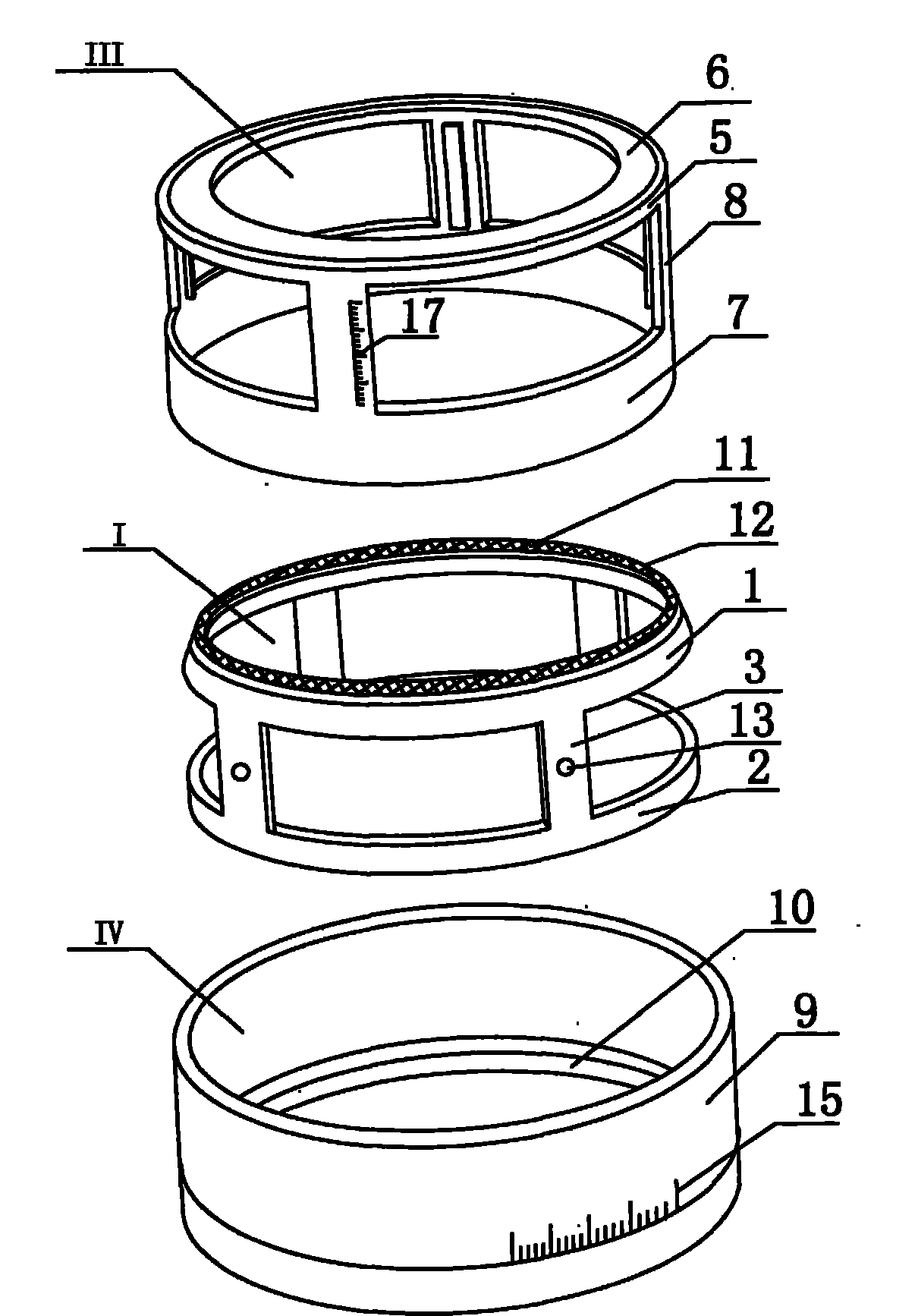
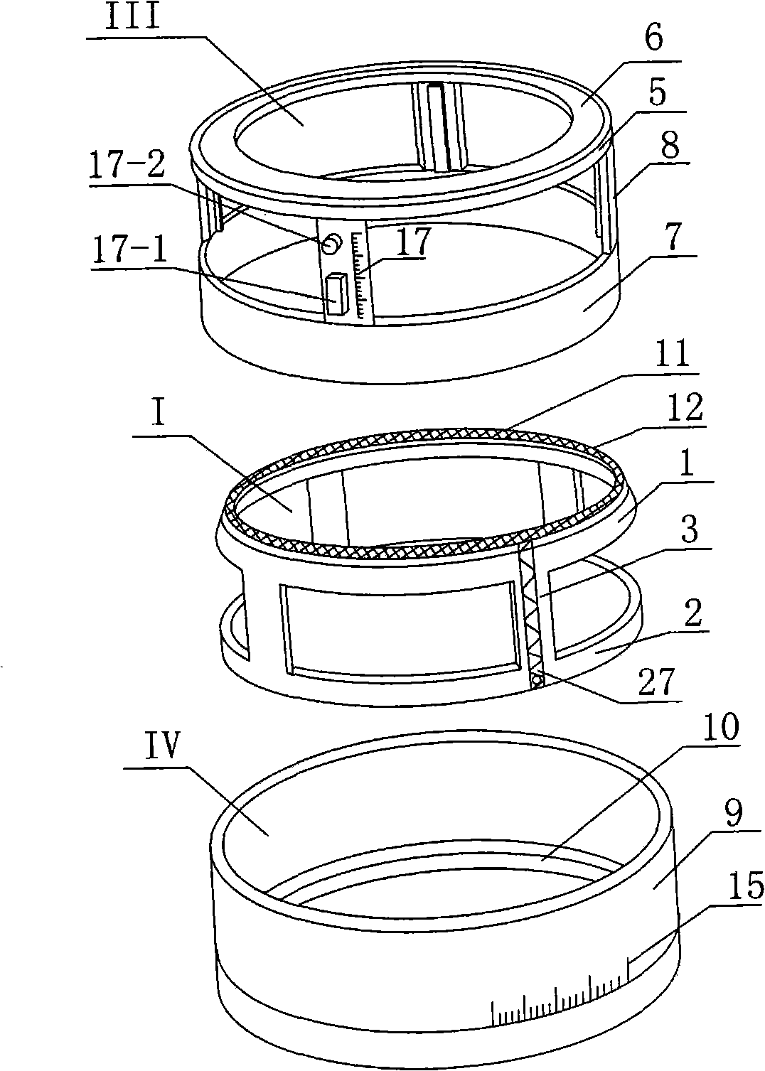
[0084] The following is a detailed description of the present invention in conjunction with the accompanying drawings. figure 1 Attached Picture 12 Shown.

[0085] The present invention is a circumcision anastomat, which comprises: an upper sleeve 1 for compressing the foreskin tissue and blood vessels in the foreskin, and end teeth 12 are evenly distributed on the upper end surface of the upper sleeve 1. The shape of 12 is a pattern 11 with concave and convex patterns, or a cross-section of a ∧-shaped tooth 12a, or a cross-section of an M-shaped tooth 12b. The teeth of different shapes are used to press the upper casing 1 and are used to connect the upper casing 1 The inner cutting ring I formed with the connecting plate 3 of the lower casing 2, the upper casing 1, the lower casing 2, and the connecting plate 3. The inner cutting ring I may be an inte...


PUM


Abstract

The invention discloses a prepuce peritomy anastomoses device which relates to a medical apparatus and is used for cutting too-long prepuces of males. The prepuce peritomy anastomoses device comprises an inner cutting ring, a tube type cutter capable of lifting, an outer cutting ring, a connecting ring and a detachable anti-erection plate arranged at the inner side of a connecting plate of the inner cutting ring, wherein the inner cutting ring is sleeved in the outer cutting ring; the tube type cutter capable of lifting is sleeved between the inner cutting ring and the outer cutting ring; a base pin on the tube type cutter passes through an arc groove on a lower ring blocking piece of the connecting ring and is connected with a knob on the tube type cutter; and the outer cutting ring is detachably connected with the connecting ring. The invention has the advantages that in the process of treating redundant prepuce and phimosis, the device brings advantages of no pain and no need of operations, no bleeding, no seaming line, no medicine taking and no fear to patients; the whole treatment process only needs several minutes, and the patient can leave the hospital after the operation without influencing works and studies of the patient; and the skin of notch is bright and clean, thus the device is popular with wide patients.

Description

[0001] This application is a divisional application. The application number of the original application document is: 200810115588.X, the filing date is: June 25, 2008, and the title of the invention is: circumcision stapler. Technical field [0002] The invention relates to a medical device, in particular to a device for removing the overly long foreskin of a male penis. Background technique [0003] Excessive foreskin or phimosis is one of the root causes of male urinary system and sexually transmitted diseases. Excessive foreskin or phimosis can cause urinary tract infection and lead to chronic prostatitis, and a series of symptoms such as backache, impotence and premature ejaculation. Therefore, removing excessively long foreskin or phimosis is one of the measures to prevent these diseases. [0004] To remove excessively long foreskin or phimosis, there have been several reforms since the beginning of our country. The first method is surgical operation, but the operation will ine...

Claims


Application Information

Patent Timeline
IPC IPC(8): A61B17/326A61M35/00
CPCA61B17/326
Inventor 商建忠商晶晶
Owner WUHU SHANGRING TECH CO LTD
Why Eureka
Try Eureka