
Agitating lorry

A technology of mixer truck and mixing drum, which is used in concrete transportation and other directions, can solve the problems of super long and high vehicle, plastic deformation, and reduced concrete loading capacity, and achieve the effect of large concrete loading capacity, reducing plastic deformation, and reducing weight.

Active Publication Date: 2010-08-25
SANY AUTOMOBILE MFG CO LTD
View PDF3 Cites 27 Cited by
  • Summary
  • Abstract
  • Description
  • Claims
  • Application Information

AI Technical Summary

Problems solved by technology

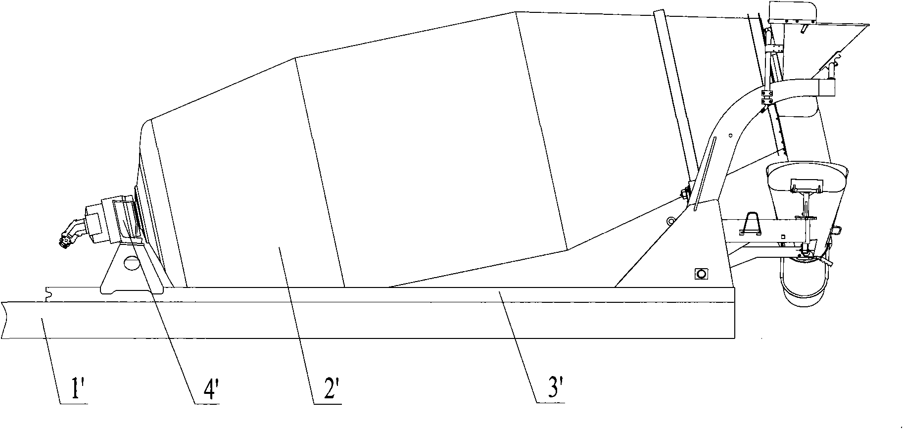
[0007] First of all, due to the increase in the loading volume of the mixing drum 2', the lengthening of the mixing drum 2', the support position of the rear cone raceway of the mixing drum 2' will be moved backward, and the distance between the support position and the center of the rear axle will increase, that is to say, the subframe The bending moment of 3' will increase, which will easily lead to plastic deformation of the main beam 32' of the sub-frame 3', and the middle part of the main beam 32' will bend upwards, resulting in the mixing drum 2' and the sub-frame 3'. Interference, making the mixing drum 2' unable to rotate normally
[0008] In order to prevent plastic deformation of the main beam of the sub-frame, those skilled in the art will often increase the size of the main beam 32', front desk 31' and backstage 32' of the sub-frame 3' to make it have sufficient bearing capacity, so that It is bound to increase the weight of the whole vehicle, which will lead to higher manufacturing cost of the whole vehicle, increased fuel consumption and reduced concrete loading
[0009] Secondly, due to the increase of the loading capacity of the mixing drum 2', it will inevitably lead to the super long and super high of the whole vehicle, especially the super high, the height of the whole vehicle will exceed the height standard of the transportation vehicle limited by road regulations, which will make this generous amount The mixer truck cannot be used
[0010] At the same time, due to the increased height of the vehicle, the center of gravity of the vehicle is relatively high, which will bring serious safety hazards to the driving of the vehicle, and will directly endanger the personal safety of operators and pedestrians on the roadside.

Method used


Image

  • Agitating lorry
  • Agitating lorry
  • Agitating lorry

Examples


Embodiment Construction

[0033] The purpose of the present invention is to provide a mixer truck. The front and back stages of the mixer truck have a small load-bearing capacity, and the frame for carrying the mixing drum bears a small bending moment, so that the frame is not prone to plastic deformation and the body No interference with the mixing drum.

[0034] In order to enable those skilled in the art to better understand the technical solutions of the present invention, the present invention will be further described in detail below with reference to the accompanying drawings and specific embodiments.

[0035] Please refer to FIGS. 3 and 4. FIG. 3 is a schematic structural diagram of a specific embodiment of the mixer truck provided by the present invention; FIG. 4 is a rear structural schematic diagram of the mixer truck in FIG. 3.

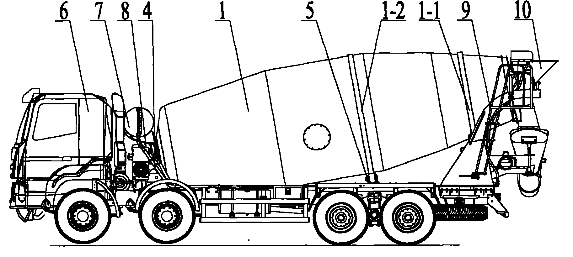
[0036] As shown in Figures 3 and 4, the mixer truck provided by the present invention includes a mixer drum 1, a backstage 2, a rear cone supporting wheel 3, a front desk...


PUM


Abstract

The invention relates to the technical field of agitating lorries, and discloses an agitating lorry. The agitating lorry comprises an agitating barrel (1), a front stand (4) and a rear stand (2); the front end of the agitating barrel (1) is supported by the front stand (4), a rear conical roller way (1-1) of the agitating barrel (1) is supported by a rear conical supporting wheel (3) fixed on the rear stand (2); the barrel body of the agitating barrel (1) is also provided with a middle roller way (1-2); and the corresponding position of a frame of the agitating lorry is provided with a middle supporting wheel (5) for supporting the middle roller way (1-2). The agitating lorry with the structure is characterized in that the middle supporting wheel (5) bears partial load of the agitating barrel (1), so the bearing capacities of the front stand (4) and the rear stand (2) are lightened, the frame is stressed uniformly, the plastic deformation and the borne bending stress of the frame are reduced, and the frame and the agitating barrel (1) do not produce interference.

Description

Technical field [0001] The invention relates to the technical field of mixer trucks, in particular to a mixer truck. Background technique [0002] Concrete mixer truck (referred to as mixer truck in this application) is a common concrete transportation equipment. The chassis of the mixer truck is equipped with a mixing drum to carry the mixed concrete. During the transportation, in order to ensure that the carried concrete will not solidify, the mixing drum must always be kept rotating. [0003] Please refer to Figure 1. Figure 1 is a schematic structural diagram of a common mixing drum arrangement in the prior art; [0004] As shown in Figure 1, a traditional mixer truck usually includes a chassis frame 1', a mixing drum 2', a subframe 3', etc. The subframe 3'is connected to the chassis frame 1'by U-shaped bolts, a backstop plate, etc. The specific structure of the subframe 3'is shown in Figure 2. The subframe 3'includes a main beam 32', a front desk 31' is provided at the front o...

Claims


Application Information

Patent Timeline
IPC IPC(8): B60P3/16
Inventor 张德春刘方兴蒋东伟
Owner SANY AUTOMOBILE MFG CO LTD
Learn More