Eureka AIR delivers breakthrough ideas for toughest innovation challenges, trusted by R&D personnel around the world.

Configuration of liquid bath pumping and filling device

A liquid tank and structure technology, applied in packaging, bottle filling, liquid filling, etc., can solve the problems of inconvenient removal of residue at the bottom of the tank, long time, and affecting work efficiency

Inactive Publication Date: 2010-08-25
ZHEJIANG JINGU CO LTD
View PDF0 Cites 1 Cited by
  • Summary
  • Abstract
  • Description
  • Claims
  • Application Information

AI Technical Summary

Problems solved by technology

In the existing liquid tank, no matter the process of filling liquid or draining liquid, it will take a long time, which obviously affects the work efficiency, and it is not convenient to remove the residue at the bottom of the tank in time

Method used


Image

  • Configuration of liquid bath pumping and filling device
  • Configuration of liquid bath pumping and filling device

Examples


Embodiment Construction

[0007] The present invention will be further described below in conjunction with the accompanying drawings and embodiments.

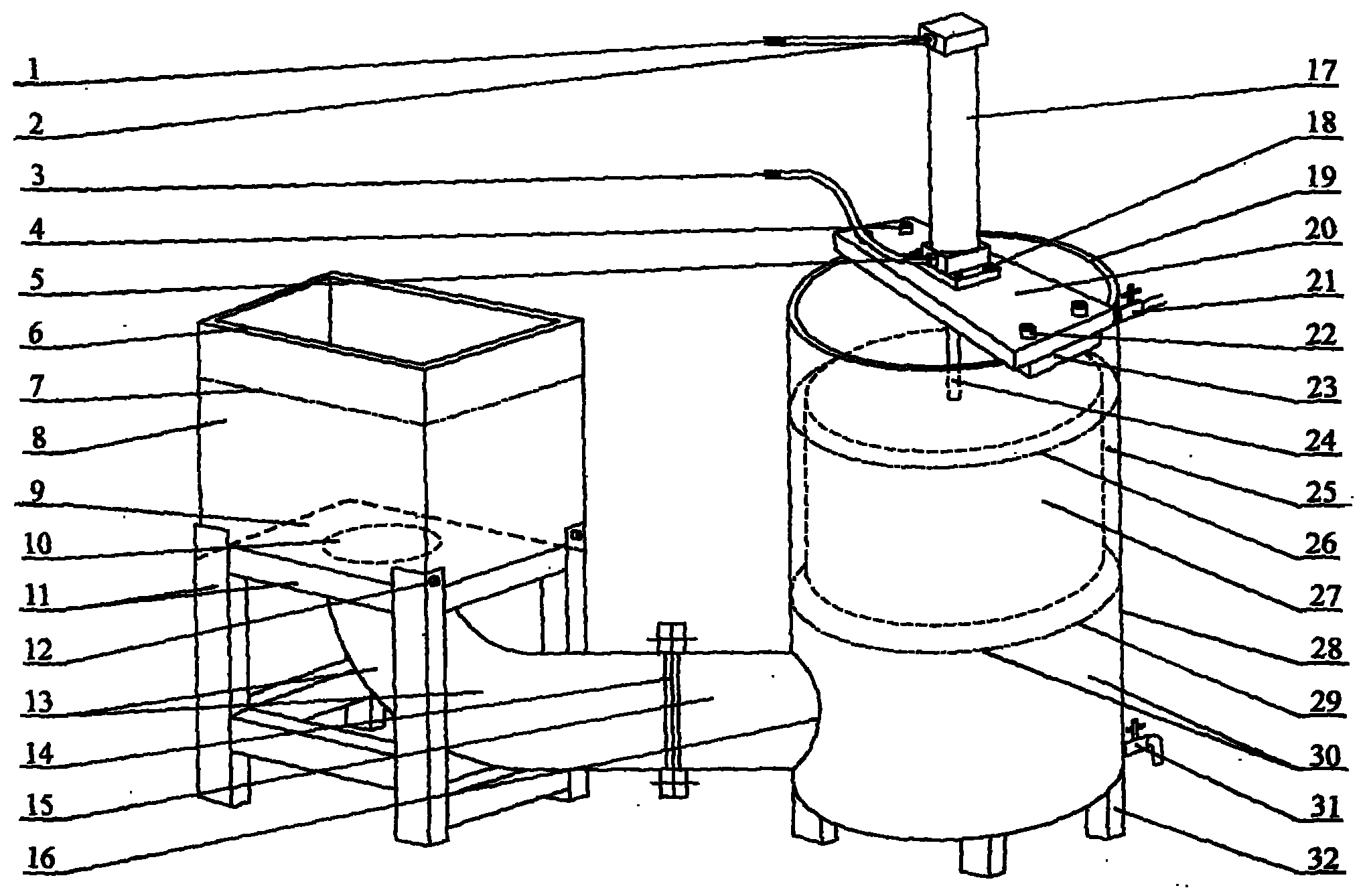
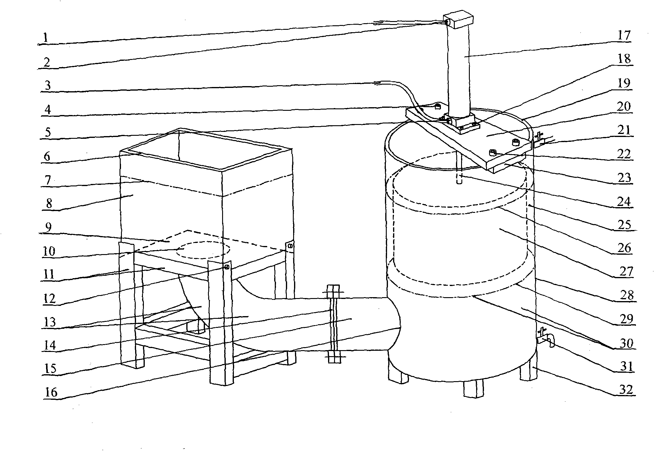
[0008] The structure of the liquid tank pumping and irrigation device is shown in the figure:

[0009] The whole is equipped with a liquid storage barrel for storing liquid, a liquid discharge assembly for discharging liquid, a fixing frame for installing the liquid discharge assembly, and a liquid pipe for filling and discharging liquid in the tank. one of them:

[0010] The liquid storage barrel comprises a barrel body 28 as shown in the figure to be a cylindrical barrel body 28, a barrel foot 32, a liquid inlet valve 21, and a drain valve 31; the barrel body 28 is connected with the barrel foot 32 at the bottom; the liquid inlet valve 21 and The blowdown valve 32 is respectively arranged on the upper part and the bottom of the barrel body 28;

[0011] Drain assembly, including cylinder 17 and telescopic rod 24, drain barrel / block 27, as shown in th...


PUM


Abstract

A configuration of liquid bath pumping and filling device is divided into a liquid storage barrel, a liquid discharge component, a fixed frame and a liquid pipe; under the premise of keeping proper gap between a liquid discharge barrel / a liquid discharge block and the inner wall of a barrel body without flowing over the liquid from a notch, the liquid amount discharged from the liquid discharge barrel / the liquid discharge block is equal to the sum of the liquid amount filled in the slot and the liquid amount of liquid level raising part in the barrel body; and the liquid is filled and discharged in the liquid bath according to the shape and size of the liquid discharge barrel / the liquid discharge block in the liquid discharge component and the pressed and lifted run length, integration of each component. In the technical scheme, a device for converting Archimedean buoyancy force into a mechanical structure is a new breakthrough of mechanical structure using basic scientific principle; the liquid discharging and filling device with high speed of liquid discharging and filling in the liquid bath is not only capable of improving the working efficiency and facilitating elimination of residues at bath bottom and barrel bottom but also capable of being applied to various technical fields such as a gas-tight detection device of a wheel, a cleaning device; and the configuration is a mechanical device with high development and application values and relatively strong universality.

Description

Technical field: [0001] The invention relates to a mechanical device, in particular to a mechanical device for filling and discharging liquid into a tank body of a liquid tank. Background technique: [0002] A common liquid tank is equipped with a liquid inlet valve and a drain valve on the tank body, and the liquid inlet valve is used to fill the tank body with liquid, and the drain valve is installed to drain the tank body. In the existing liquid tank, no matter the liquid filling process or the liquid draining process, it will take a long time, which obviously affects the work efficiency, and it is also inconvenient to remove the residue at the bottom of the tank in time. Invention content: [0003] The object of the present invention is to provide a structure of a liquid tank pumping and irrigating device. The fixed frame, the liquid pipe used for filling and draining the tank, and based on the premise of maintaining a proper gap between the drain barrel / drain block a...

Claims


Application Information

Patent Timeline
Patent Type & Authority Applications(China)
IPC IPC(8): B67C3/34B67C9/00
Inventor 孙金国孙锋峰
Owner ZHEJIANG JINGU CO LTD
Why Eureka
Eureka Blog
Learn More