Thermal equipment for producing composite ceramic solar panel

A technology of ceramic plates and heat-resistant baffles is applied in lighting and heating equipment, ceramic material production, heating to dry solid materials, etc. , to achieve the effect of improving production efficiency and yield, reducing heat conduction distance and stabilizing production

Inactive Publication Date: 2011-10-26
曹树梁
View PDF5 Cites 0 Cited by
  • Summary
  • Abstract
  • Description
  • Claims
  • Application Information

AI Technical Summary

Problems solved by technology

[0005] The main disadvantages of vacuum glass tubes are: the vacuum glass tube is composed of coaxial inner and outer glass tubes, one end is closed, the inner and outer tubes are vacuumed, the outer tube is transparent, and the outer surface of the inner tube is covered with solar absorbing paint
[0007] The main disadvantages of the copper tube plate solar collector are: the sunlight absorption rate of the solar absorbing coating is easy to attenuate; the copper material is very expensive and requires electrolytic purification, and the manufacturing cost and energy consumption are high; the heat collecting copper tube has a large horizontal interval and a long heat conduction distance , affect the efficiency; the weld is easy to corrode; the general effective service life is 10-25 years
However, the existing solar collectors have high manufacturing costs and short effective service life, which makes the cost of using solar energy much higher than conventional energy sources, which seriously restricts the development of solar collectors. Solar collectors must be integrated with buildings. In order to obtain greater development space, the existing solar collectors are restricted by the materials and structures of their solar collectors, and it is difficult to achieve integration with buildings

Method used


Image

  • Thermal equipment for producing composite ceramic solar panel
  • Thermal equipment for producing composite ceramic solar panel
  • Thermal equipment for producing composite ceramic solar panel

Examples


Embodiment Construction

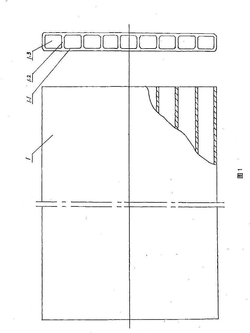
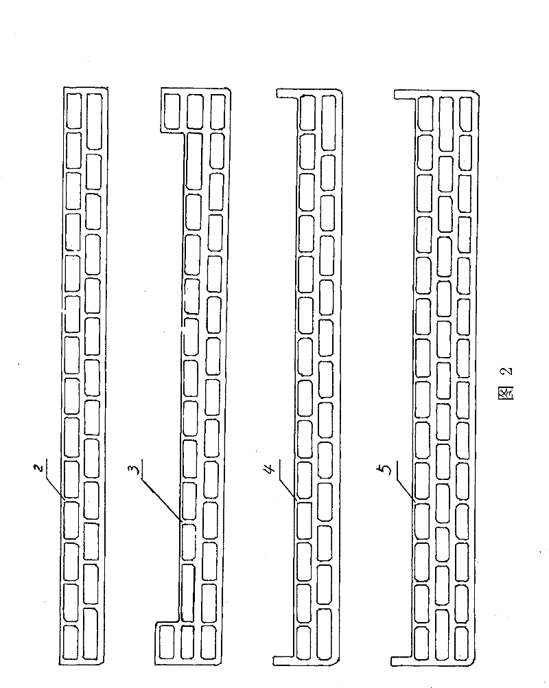
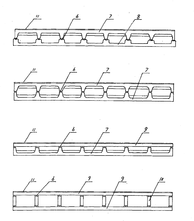
[0059] 1. The roller kiln is used for drying the hollow ceramic slab blanks with through-hole flat box structure. A movable baffle is installed in the hearth of the roller kiln. The position of the baffle can be adjusted to change the cross-sectional area of ​​the furnace. The baffle is positioned by the boom and the cam. Lift the boom or turn the cam to raise and lower the flat baffle and change the angle of the inclined baffle. The movable baffle, boom and cam are made of stainless steel. Adjust the position of the baffle to make the hollow ceramic The inner and outer surfaces of the slab are dried simultaneously.

[0060] 2. The roller kiln used for firing the through-hole flat box structure hollow ceramic slab green body. A movable baffle is installed in the hearth of the roller kiln. The position of the baffle can be adjusted to change the cross-sectional area of ​​the furnace. The movable baffle is positioned by the boom and the cam. Lift the boom or turn the cam to rais...


PUM

PropertyMeasurementUnit
thicknessaaaaaaaaaa

Abstract

The invention relates to a structure of a solar thermal collector, ceramic industry in China, a composite ceramic solar panel production technology and thermal equipment. The invention fully utilizes the common roller kiln for drying and firing in ceramic industry; movable heat-resisting baffles are installed in the hearth of the roller kiln; the positions of the baffles can be adjusted to convert the area of the cross section of the hearth; the movable baffles in the hearth of the roller kiln are positioned by a hanger rod and a cam; the hanger rod is elevated or the cam is rotated to elevate the horizontal baffle or change the angle of the sloping baffle, thereby changing the movement path of the heat current; thus, part of the heat current enters through holes of the hollow ceramic plate blank, so that the inner surface and the outer surface of the outer wall of the hollow ceramic plate blank, and both surfaces of the support wall are in the same heating state, thereby greatly shortening the thermal conduction distance; and therefore, all parts of the hollow ceramic plate blank are in the same temperature, drying or firing state, thereby greatly enhancing the production efficiency for drying and firing the hollow ceramic plate blanks and increasing the yield.

Description

technical field [0001] The present invention relates to solar heat collectors, ceramic solar heat collectors, composite ceramic solar panels, ceramic plates with equal cross-sections and through holes, especially a flat box with equal cross-sections and through holes with ordinary ceramics as the substrate and black porcelain as the sunlight absorbing layer Thermal equipment for the production of composite ceramic solar panels. Background technique [0002] Solar energy utilization includes photoelectric utilization and photothermal utilization. Photoelectric utilization mainly refers to solar cells, and photothermal utilization mainly refers to concentrated solar power generation devices and solar collectors. The most widely used solar collector is solar water heaters, and the key components are solar collectors. hot body. my country mainly uses vacuum glass tube solar collectors, see Figure 10 , Europe, the United States, Japan, Australia and other countries mainly use c...

Claims


Application Information

Patent Timeline
Patent Type & Authority Patents(China)
IPC IPC(8): F27B9/00F27B9/10F27B9/30F26B15/12F26B3/02C04B35/64
CPCY02P40/60
Inventor 曹树梁许建华蔡滨王启春石延岭许建丽修大鹏杨玉国谷胜利
Owner 曹树梁
Why Eureka
Try Eureka