Hardening equipment and method for manufacturing liquid crystal display panel

A liquid crystal display panel and equipment technology, applied in the field of liquid crystal display panel manufacturing and hardening equipment

Active Publication Date: 2011-08-10
K TRONICS (SUZHOU) TECH CO LTD +1
View PDF4 Cites 0 Cited by
  • Summary
  • Abstract
  • Description
  • Claims
  • Application Information

AI Technical Summary

Problems solved by technology

[0014] The object of the present invention is to provide a hardening device and a manufacturing method of a liquid crystal display panel to overcome the equipment cost caused by the enlargement of the liquid crystal panel in the prior art Raised defects

Method used


Image

  • Hardening equipment and method for manufacturing liquid crystal display panel
  • Hardening equipment and method for manufacturing liquid crystal display panel
  • Hardening equipment and method for manufacturing liquid crystal display panel

Examples


no. 1 example

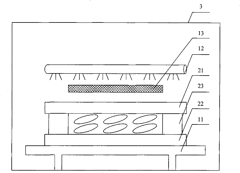
[0040] image 3 It is a schematic diagram of the first embodiment of the hardening device of the present invention. Such as image 3 Shown, hardening equipment of the present invention comprises:

[0041] The workbench 11 is used to place the panel and is located at the bottom of the reaction chamber 3. The workbench 11 is provided with a first area and a second area surrounded by the first area, and the first area and the panel are The non-display area corresponds to the adhesive in the panel, the second area corresponds to the display area of ​​the panel, and the workbench 11 is provided with a heating device;

[0042] Ultraviolet lamp 12, is used for vertically irradiating the whole workbench 11, and is positioned at the top of described reaction chamber 3;

[0043] The light blocking plate 13 is used to cover the second area of ​​the workbench 11 , that is, to cover the display area of ​​the panel, and is located below the ultraviolet lamp 12 .

[0044] In the hardenin...

no. 2 example

[0047] Figure 4 It is a schematic diagram of the second embodiment of the hardening device of the present invention. Such as Figure 4 Shown, hardening equipment of the present invention comprises:

[0048]The workbench 11 is used to place the panel and is located at the bottom of the reaction chamber 3. The workbench 11 is provided with a first area and a second area surrounded by the first area, and the first area and the panel are Corresponding to the non-display area, that is, corresponding to the adhesive in the panel, the second area corresponds to the display area of ​​the panel, and a ventilation duct 42 is opened in the workbench 11, and the ventilation duct 42 is provided with Air blowing holes 43 are used to blow hot air into the ventilation duct. The ventilation duct 42 is provided with air suction holes 44 for extracting hot air from the ventilation duct. The ventilation duct 42 passes through the air blowing holes 43 Connect with the air suction hole 44 and t...

no. 3 example

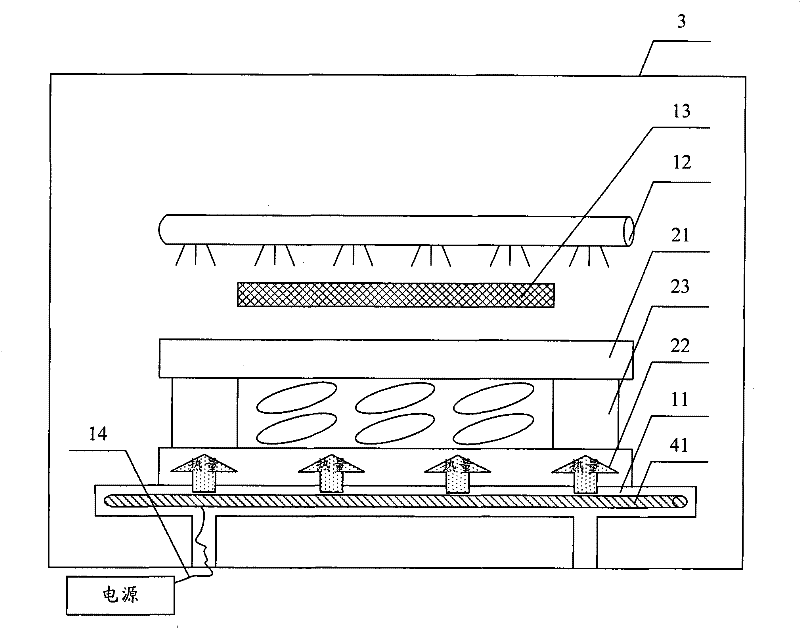
[0053] Figure 5 It is a schematic diagram of the third embodiment of the hardening device of the present invention. Such as Figure 5 Shown, hardening equipment of the present invention comprises:

[0054] The workbench 11 is used to place the panel and is located at the bottom of the reaction chamber 3. The workbench 11 is provided with a first area and a second area surrounded by the first area, and the first area and the panel are The non-display area corresponds, that is, corresponds to the adhesive in the panel, the second area corresponds to the display area of ​​the panel, and the workbench 11 is a transparent workbench, such as a glass substrate, a quartz substrate, etc., and An infrared lamp 45 is arranged under the workbench, that is, an infrared lamp 45 is arranged under the glass substrate to irradiate the panel evenly;

[0055] The ultraviolet lamp 12 is used to vertically irradiate the entire workbench 11 and is located on the top of the reaction chamber 3; ...


PUM


Abstract

The invention relates to hardening equipment and a method for manufacturing a liquid crystal display panel. The hardening equipment comprises a response cabin, a workbench, an ultraviolet lamp and a light barrier, wherein the workbench is positioned at the bottom of the response cabin and is provided with a first area and a second area which is enclosed by the first area; the first area corresponds to a non-display area of the panel; the second area corresponds to a display area of the panel; the ultraviolet lamp is positioned on the top of the response cabin and is used for irradiating the workbench; the light barrier is positioned below the ultraviolet lamp and is used for shielding the second area of the workbench; and the workbench is provided with a heating device. By using a method of arranging the heating device on the workbench, the hardening equipment of the invention can perform heat treatment on an adhesive at the same time in the process of hardening the adhesive by using ultraviolet rays, thereby overcoming the defect of the increasing of equipment cost caused by the large scale of liquid crystal panels in the prior art.

Description

technical field [0001] The invention belongs to the fields of liquid crystal display devices and manufacturing equipment, and in particular relates to a curing device used in the manufacturing process of a liquid crystal display device and a method for manufacturing a liquid crystal display panel using the curing device. Background technique [0002] A liquid crystal display device (Liquid Crystal Display, referred to as LCD) is a main flat panel display device (Flat Panel Display, referred to as FPD). [0003] Liquid crystal display devices are classified into vertical electric field type liquid crystal display devices and horizontal electric field type liquid crystal display devices according to the direction of an electric field for driving liquid crystals. Vertical electric field type liquid crystal display devices include: twisted nematic (TwistNematic, referred to as TN) type liquid crystal display devices; horizontal electric field type liquid crystal display devices ...

Claims


Application Information

Patent Timeline
Patent Type & Authority Patents(China)
IPC IPC(8): G02F1/1333C09J5/00
CPCG02F1/1341G02F2201/086G02F2202/023G02F1/1303
Inventor 宋省勲
Owner K TRONICS (SUZHOU) TECH CO LTD
Why Eureka
Try Eureka