
an electronic motor

An electronic and stator technology, applied in the direction of electrical components, electromechanical devices, electric components, etc., can solve the problems of high cost of metal shell, large eddy current heat loss, affecting motor efficiency, etc.

Active Publication Date: 2017-01-25
东莞艾科机电设备有限公司 +1
View PDF3 Cites 0 Cited by
  • Summary
  • Abstract
  • Description
  • Claims
  • Application Information

AI Technical Summary

Problems solved by technology

When the magnetic flux passes through the narrow section of the sheet, the eddy current is limited to flow along some narrow circuits in each sheet, the net electromotive force in these circuits is small, the length of the circuit is large, and because the resistivity of the sheet material is large , so that the eddy current loss can be significantly reduced; but the eddy current of this stator is still very large, and the eddy current heat loss is large, which affects the efficiency of the motor
Most of the existing electronic motors use metal casings, and the power cord passes through the connecting hole of the metal casing, and then is fixed in the casing by a ring nut. However, the cost of this metal casing is high and the complexity of assembly is replaced by a plastic casing. Traditional metal enclosures, however, are not likely to hold power cords securely as plastics are easily deformed, nor can they ensure a degree of sealing that is adequate for the purpose of the motor, such as for refrigeration units

Method used


Image

  • an electronic motor
  • an electronic motor
  • an electronic motor

Examples


Embodiment Construction

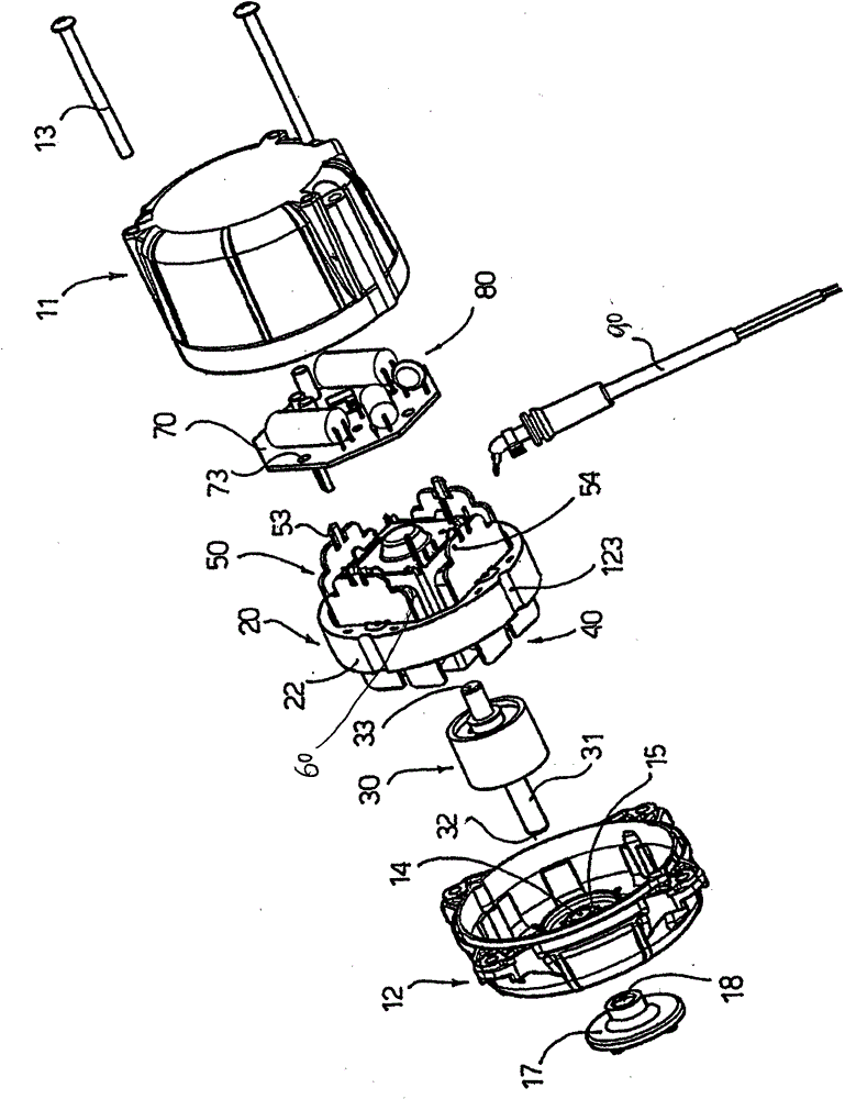
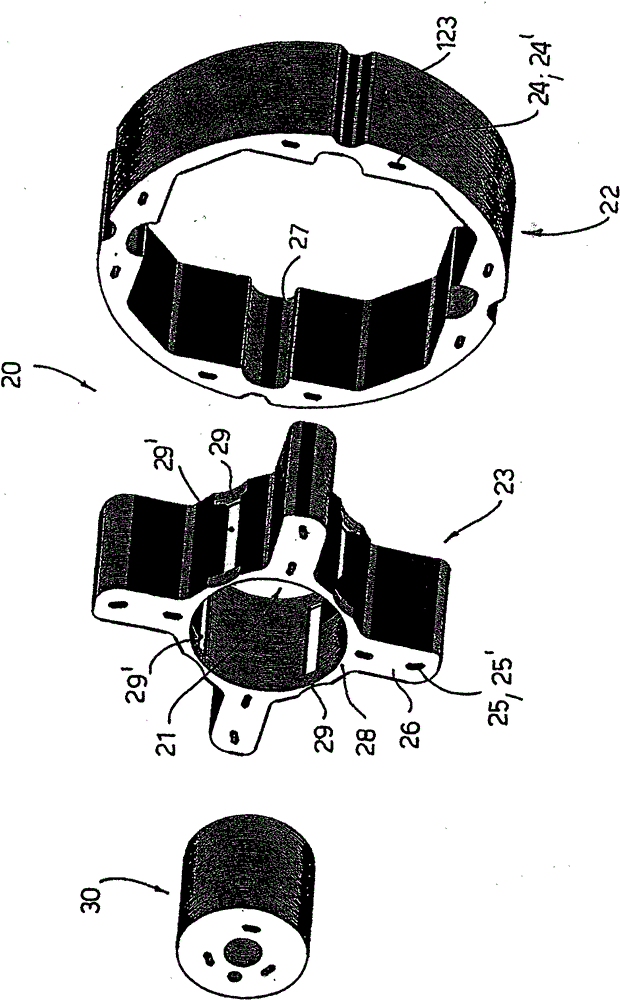
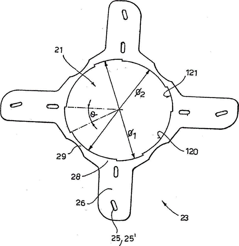
[0033] figure 1 , 2 , 3, 4, 5, and 6, the electronic motor of the present invention includes a front half shell 12, a rear half shell 11, a stator 20 with a winding 60, a rotor 30 with a shaft coupling 31, and a rear insulating support 50. The circuit board 70 and the power cord 90 installed on the rear insulating bracket 50. The stator 20 is composed of a stator fork 22 and a pole piece 23. A through hole 21 is provided in the middle of the pole piece 23, and pole shoes 28 are extended around it. The pole shoe 28 is provided with a radial electrode 26, and the inside of the stator fork 22 is provided with a slot 27 adapted to the pole piece electrode 26. The stator fork 22 and the pole piece 23 are plugged together through the slot 27 and the electrode 26. The pole shoe 28 has a large arched edge 120 on which a recess 121 is provided, the inner diameter of which is slightly larger than the inner diameter of the edge of the pole shoe 28 . The size of the above-mentioned conc...


PUM


Abstract

The invention discloses an electronic motor, comprising a stator, a rotor, a rear insulating bracket and a circuit board. The stator consists of a stator fork and a pole piece, wherein the center of the pole piece is provided with a through hole, and a pole shoe extends from the periphery of the pole piece. A radial electrode is arranged at the pole shoe which is provided with a larger arched edge, a formed concave part is arranged at the arched edge, and the inner diameter of the concave part is slightly larger than that of the edge of pole shoe. The invention also discloses a shell of the electronic motor, comprising a casing which consists of a shell, an end cover matched with the shell and a power line, wherein the shell is provided with a notch, one end of the power line connected with the shell is provided with a base adaptive with the notch of the shell, the periphery of the base matched with the notch is provided with a guide slot, and the power line and the shell are spliced together through the guide slot and the edge of the notch. The invention improves the efficiency of the motor and effectively solves the problem that the fixation of plastic shell and the power line is infirm.

Description

technical field [0001] The invention relates to the technical field of motors, in particular to an electronic motor. Background technique [0002] In the existing electronic motor, since the stator generates a large eddy current when it is energized, the stator heats up, causing a large eddy current loss. To reduce eddy current loss. Made of laminated sheets. These sheets are coated with a thin layer of insulating varnish or insulating oxide. When the magnetic flux passes through the narrow section of the sheet, the eddy current is limited to flow along some narrow circuits in each sheet, the net electromotive force in these circuits is small, the length of the circuit is large, and because the resistivity of the sheet material is large , so that the eddy current loss can be significantly reduced; but the eddy current of the stator is still large, and the eddy current heat loss is large, which affects the efficiency of the motor. Most of the existing electronic motors us...

Claims


Application Information

Patent Timeline
Patent Type & Authority Patents(China)
IPC IPC(8): H02K1/12H02K5/00H02K11/00H02K11/20
Inventor 恩佐·科伦波
Owner 东莞艾科机电设备有限公司
Learn More