Gate driving circuit
A gate drive circuit and circuit technology, used in electrical components, electronic switches, and adjusting electrical variables, etc., can solve the problems of slow rise of constant current, deviation of conduction loss, inability to thermal design, etc., to achieve reduction of raw materials, efficient thermal Design and effect of suppressing variation in conduction loss
- Summary
- Abstract
- Description
- Claims
- Application Information
AI Technical Summary
Problems solved by technology
Method used
Image
Examples
Embodiment approach 1
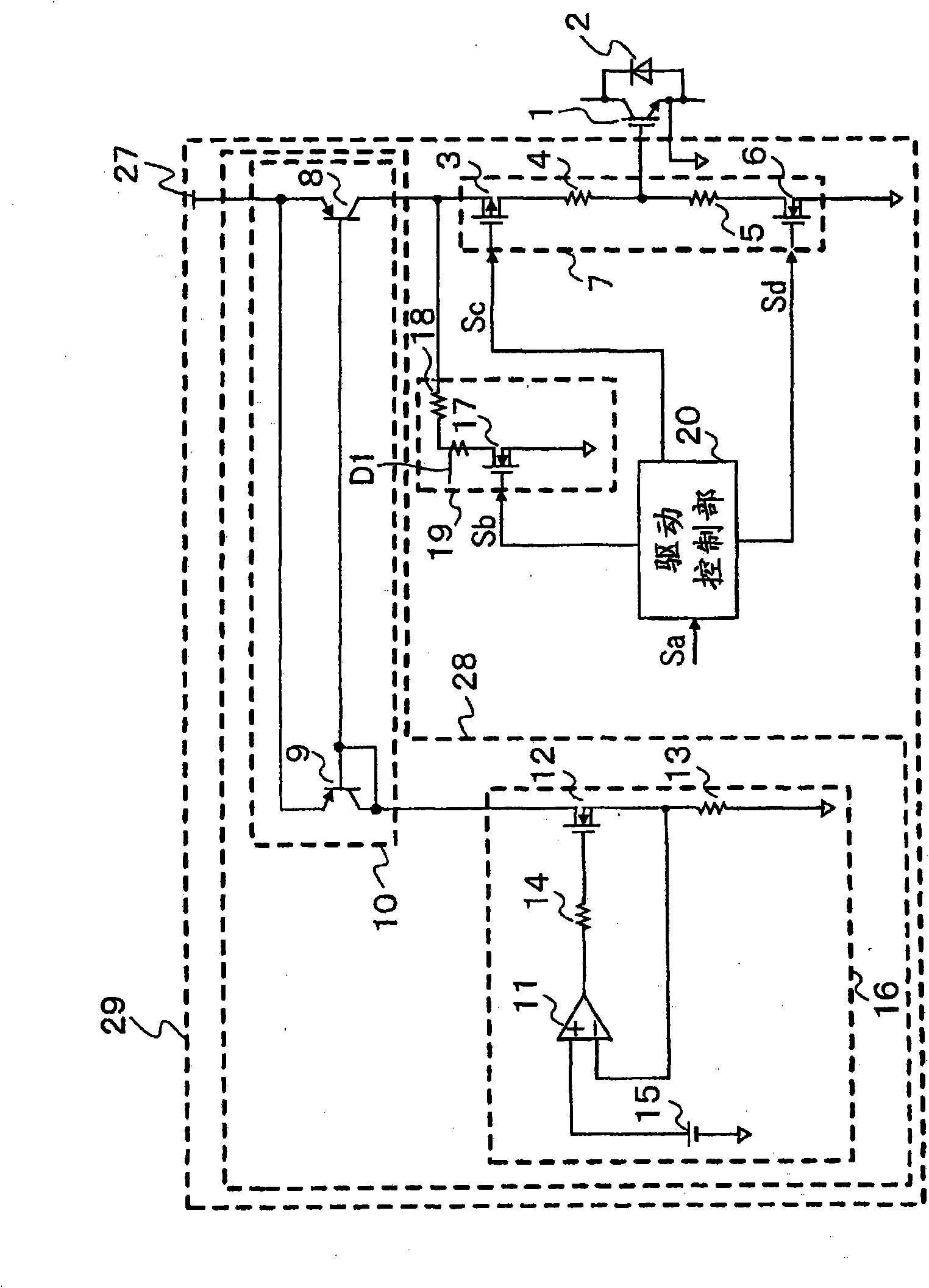
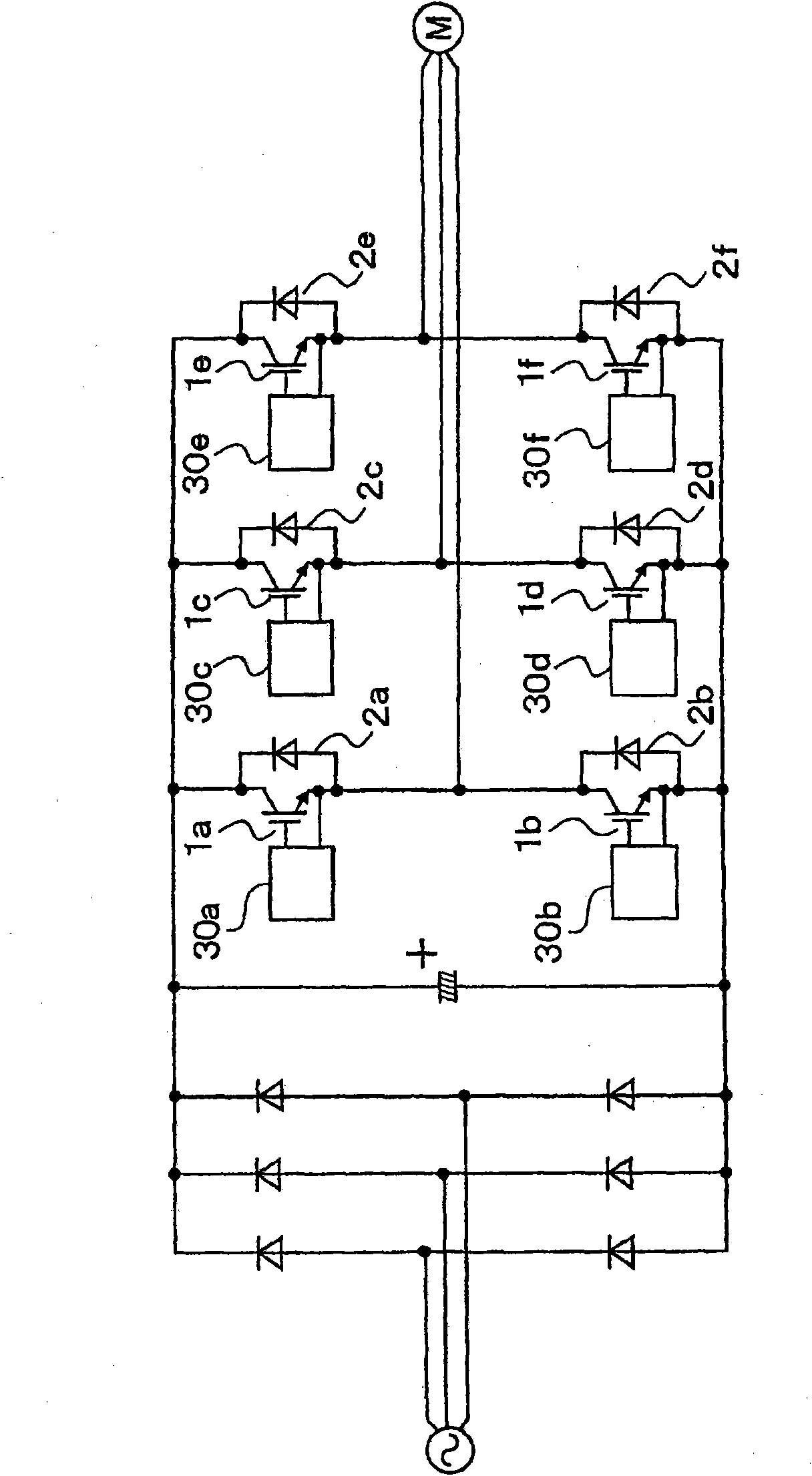
[0027] FIG. 1 is a circuit diagram of a gate drive circuit according to Embodiment 1 of the present invention. As the semiconductor element 1 for power, an IGBT1 (Insulated Gate Bipolar Transistor, insulated gate bipolar transistor) is used. However, not limited to IGBTs, even if they are composed of other switches such as FET (Field Effect Transistor) or switches using not only silicon but also other materials such as silicon carbide (SiC) and gallium nitride (GaN), the same The effect is self-evident. The combination of IGBT1, diode 2, and gate drive circuit 29 described here can be used in various power converters such as the three-phase inverter circuit shown in FIG. 2 .
[0028] In FIG. 2 , 1a to 1f denote power semiconductor devices (IGBTs), 2a to 2f denote diodes, and 30a to 30f denote gate drive circuits. The gate drive circuits 30a to 30f control the switching of the power semiconductor elements 1a to 1f with respect to the current obtained from the AC power supply ...
Embodiment approach 2
[0046] 6 is a circuit diagram showing a gate drive circuit according to Embodiment 2 of the present invention. In FIG. 6 , the same or corresponding parts as those of the above-described embodiment are denoted by the same or related symbols, and description thereof will be omitted. In the gate drive circuit 29a of FIG. 6, the preliminary energization circuit 19a is connected to the gate terminal of the IGBT1, and the preliminary energization circuit 19a is composed of an N-channel type MOSFET 17a as a second switch that controls the current to the gate terminal of the IGBT1. and resistor 18a. The drain of N-channel MOSFET 17a is connected to the gate terminal of IGBT1 via resistor 18a, the gate is connected to drive control unit 20, and the source is connected to the ground side.
[0047] FIG. 7 is a timing chart for explaining the operation of the circuit in FIG. 6 . (a) of FIG. 7 shows the control command signal Sa, (b) shows the control command signal Sb, (c) shows the co...
Embodiment approach 3
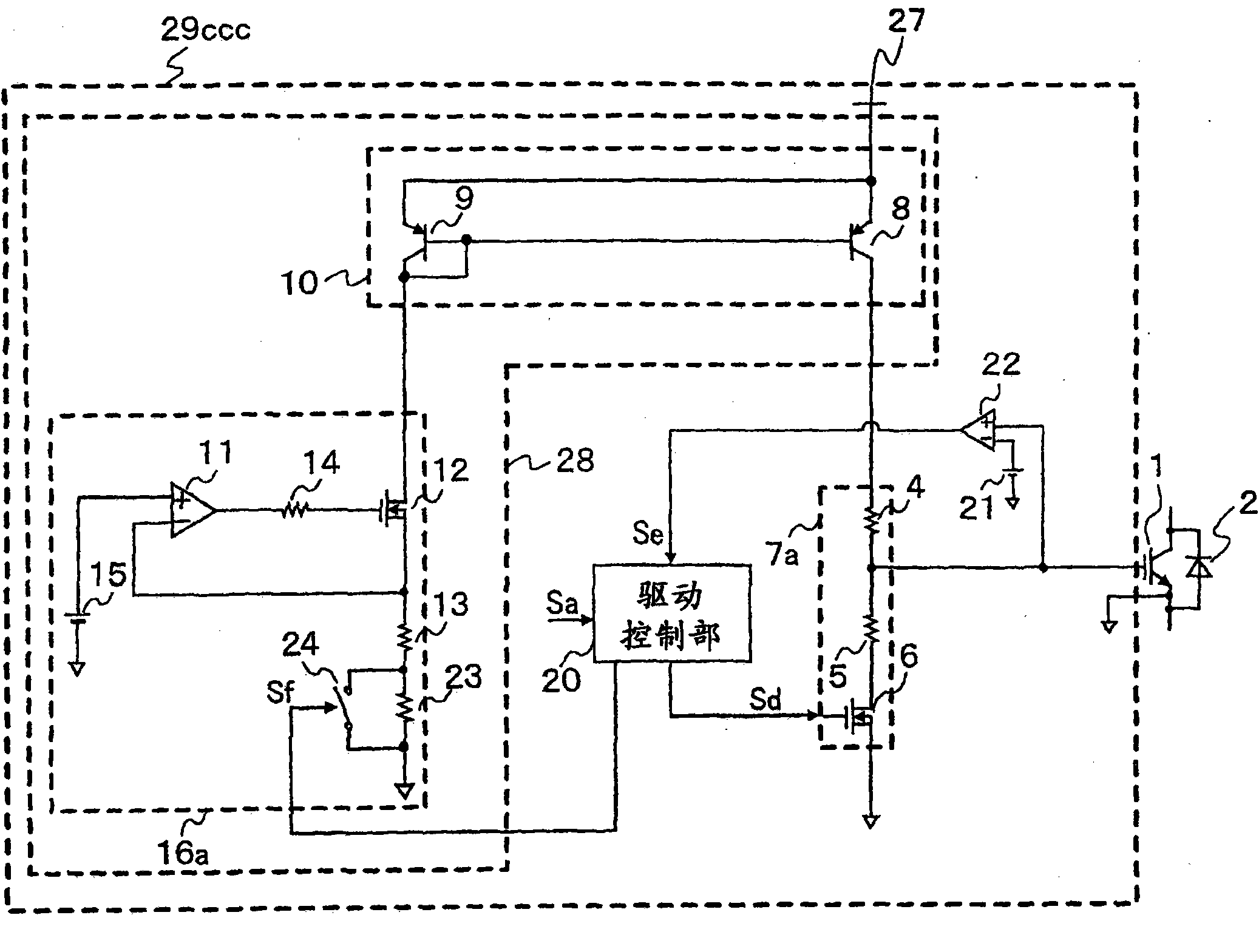
[0053] 8 is a circuit diagram of a gate drive circuit according to Embodiment 3 of the present invention. In FIG. 8 , the same or corresponding parts as those in the above-described embodiment are denoted by the same or related symbols, and description thereof will be omitted. In the gate drive circuit 29 b of FIG. 8 , the constant current circuit 16 a is normally set to a small current, and is set to a large current only when necessary. Therefore, a resistor 23 is connected in series with the setting resistor 13 for setting the constant current value of the constant current circuit 16a, and a switch 24 for short-circuiting both ends of the resistor 23 is connected in parallel with the resistor 23. Furthermore, comparators 22 and 26 are provided, and the comparators 22 and 26 are connected to the gate terminal of the IGBT 1 and compare the gate voltage with a preset voltage.
[0054] The first reference power source 21 that generates the first reference voltage and the compar...
PUM
 Abstract
Description
Claims
Application Information
 - R&D
- Intellectual Property
- Life Sciences
- Materials
- Tech Scout
- Unparalleled Data Quality
- Higher Quality Content
- 60% Fewer Hallucinations
Browse by: Latest US Patents, China's latest patents, Technical Efficacy Thesaurus, Application Domain, Technology Topic, Popular Technical Reports.
© 2025 PatSnap. All rights reserved.Legal|Privacy policy|Modern Slavery Act Transparency Statement|Sitemap|About US| Contact US: help@patsnap.com


