
Control system and control method for tapping and slagging of converter

A technology of control system and control method, which is applied in the direction of sequence/logic controller program control, electrical program control, manufacturing converter, etc., which can solve the problem of inability to accurately and timely discover the slag situation of the converter, short service life, and slag blocking Poor effect and other problems, to achieve the effect of reducing the amount of slag in converter tapping, long service life and convenient maintenance

Active Publication Date: 2010-09-01
MAANSHAN IRON & STEEL CO LTD
View PDF2 Cites 32 Cited by
  • Summary
  • Abstract
  • Description
  • Claims
  • Application Information

AI Technical Summary

Problems solved by technology

In the method of sealing the tapping hole, the floating ball and floating dart system needs to use manual or special equipment to put the plugging device into the molten pool near the tapping hole in the furnace. Since the slag of the converter cannot be accurately and timely detected, resulting in blocking Slag effect is poor
Sliding gate valve system and pneumatic slag retaining system have disadvantages such as complicated maintenance, easy damage, short service life and high price
[0008] At present, the slag detection combined with slag blocking technology developed at home and abroad mainly uses electromagnetic method combined with sliding gate valve, pneumatic or slag blocking dart system to block slag, all of which have defects such as complex system, expensive price, and easy damage

Method used


Image

  • Control system and control method for tapping and slagging of converter
  • Control system and control method for tapping and slagging of converter
  • Control system and control method for tapping and slagging of converter

Examples


Embodiment Construction

[0042] Referring to the accompanying drawings, through the description of the embodiments, the specific implementation of the present invention, such as the shape, structure, mutual position and connection relationship between the various parts, the function and working principle of each part, and the manufacturing process And the method of operation and use, etc., are described in further detail to help those skilled in the art have a more complete, accurate and in-depth understanding of the inventive concept and technical solution of the present invention.

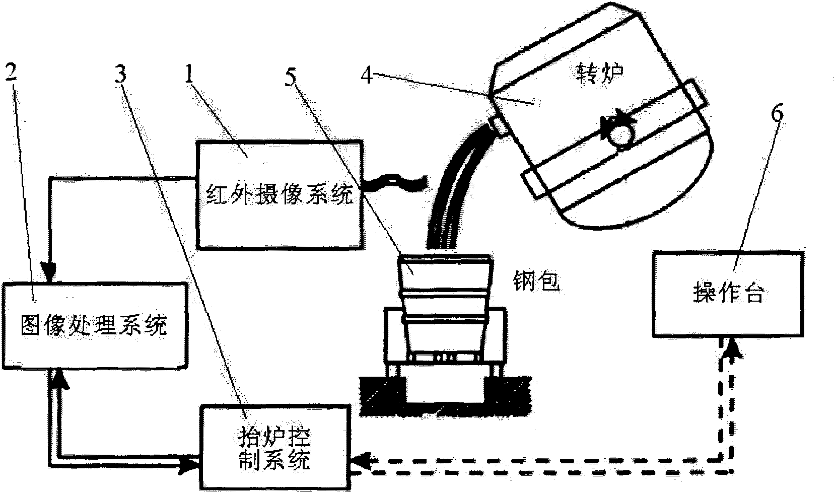
[0043] like figure 1 The structure of the present invention expressed is that the present invention is a control system for tapping and slag removal in a converter, which includes a converter 4 , a ladle 5 and an operating platform 6 .

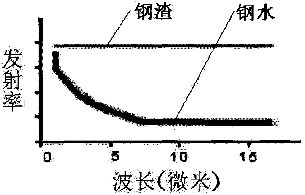
[0044] figure 2 It reflects the emissivity curve of converter 4 molten steel and slag at 1600 °C. It can be seen that the emissivity of converter 4 molten steel and slag is significant...


PUM


Abstract

The invention discloses a control system for tapping and slagging of a converter, which comprises the converter (4), a ladle (5), and a console (6). A slagging detection system and an automatic converter-lifting control system (3) are arranged in the control system; and the slagging detection system comprises a thermal infrared imaging detection system (1) and an image analyzing and processing system (2). By adopting the technical scheme of a thermal infrared imaging method, converter slagging conditions can be detected in time; slag can be stopped in combination with a slag-stopping ball at the same time; converter tapping conditions can be continuously monitored in real time; the slag and molten steel can be distinguished accurately; the response speed is high; and the timely judgment, timely converter-shaking and timely addition of the slag-stopping ball can be realized so as to reduce the tapping and slagging amount of the converter. The control system has the advantage of long service life because equipment is far away from a converter body, reliable operation, no need of visual observation of workers, convenient maintenance and few space requirements.

Description

technical field [0001] The invention belongs to the technical field of metallurgical industry production, and relates to converter steelmaking production equipment in iron and steel industry production. More specifically, the invention relates to a control system for tapping and slag removal of converters. In addition, the present invention also relates to a control method adopted by the control device. Background technique [0002] Converter tapping slag will bring many adverse effects on the quality of molten steel, such as: reducing the alloy yield; reducing the life of the ladle refractory material; causing molten steel rephosphorization and reoxidation; increasing the processing time of the refining process, etc. [0003] In order to realize as little converter slag as possible flowing into the ladle, real-time detection and control of converter slag must be carried out. At present, during the tapping process of most steelmaking plants at home and abroad, the control o...

Claims


Application Information

Patent Timeline
IPC IPC(8): C21C5/46G05B19/04
CPCY02P10/25
Inventor 孙维汪开忠吴坚汤寅波徐葆春王卓
Owner MAANSHAN IRON & STEEL CO LTD
Learn More