
High-resolution frequency measurement method with continuous counting interval marking

A high-resolution, frequency measurement technology, applied in the field of signal processing, can solve problems such as improving resolution, high resolution, and increasing circuit complexity, counting speed, etc.

Inactive Publication Date: 2010-09-01
TIANJIN AGRICULTURE COLLEGE
View PDF5 Cites 10 Cited by
  • Summary
  • Abstract
  • Description
  • Claims
  • Application Information

AI Technical Summary

Problems solved by technology

[0003] To sum up, the resolution of frequency measurement by direct counting method is related to the frequency to be measured. If the frequency to be measured is high, the resolution is high, and vice versa. When the frequency to be measured is constant, the resolution can only be improved by prolonging the measurement time. Will affect the real-time performance of the measurement
The resolution of frequency measurement by indirect counting method is related to the reference frequency. If the reference frequency is high, the resolution will be high, and vice versa. The resolution can be improved by increasing the reference frequency, but it is subject to the reference frequency specification (it can be improved by frequency multiplication, but increasing The complexity of the circuit) and the limitation of counting speed; when the reference frequency is determined, the resolution can only be improved by prolonging the measurement time, which also affects the real-time performance of the measurement
Interpolation frequency measurement can obtain high resolution, but the existing problems are complex circuit, low reliability and high cost
The continuous sampling time marking method can also obtain high resolution, but the relative measurement time is long, and the change of the frequency to be measured during the measurement period will seriously affect the improvement of the resolution

Method used

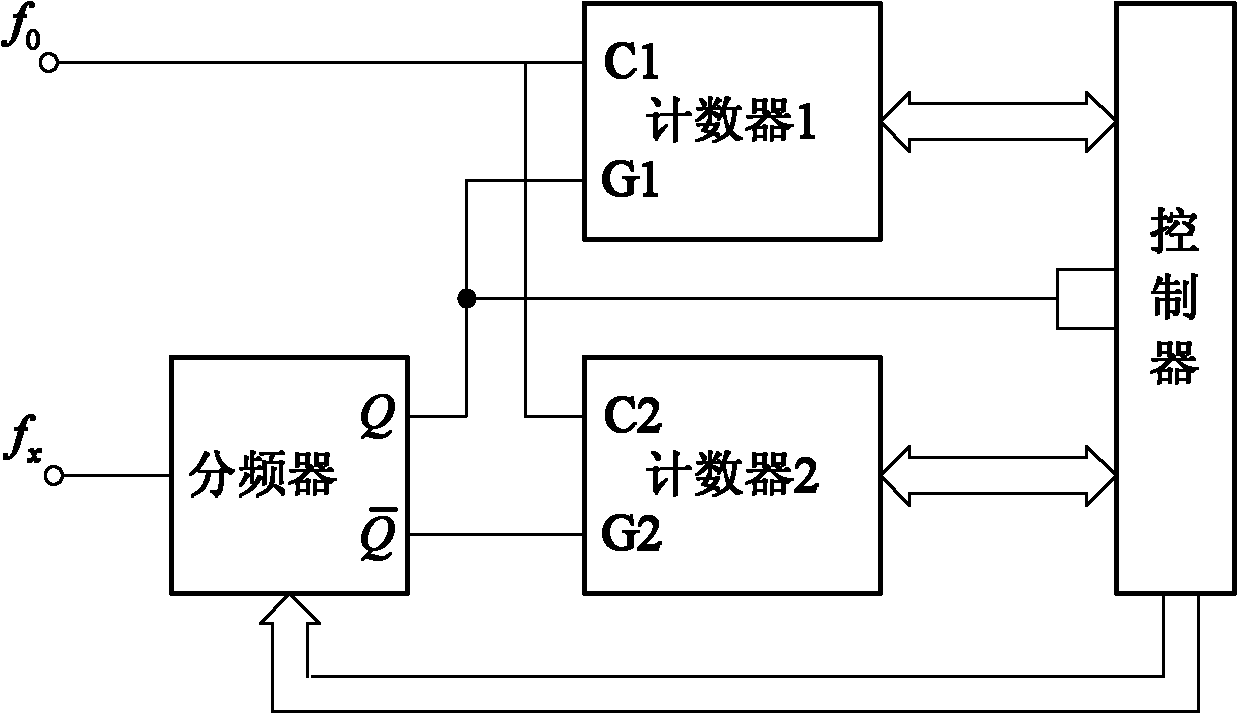
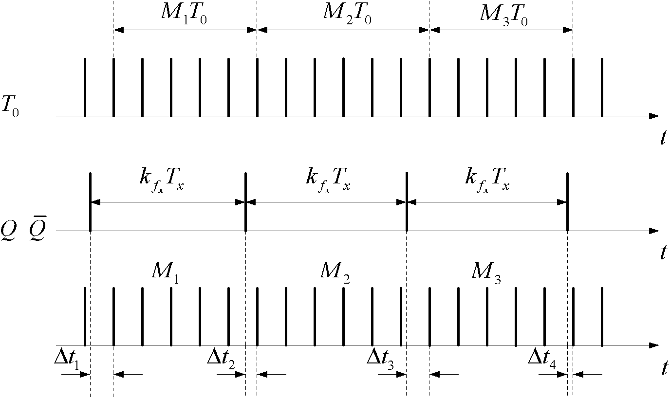
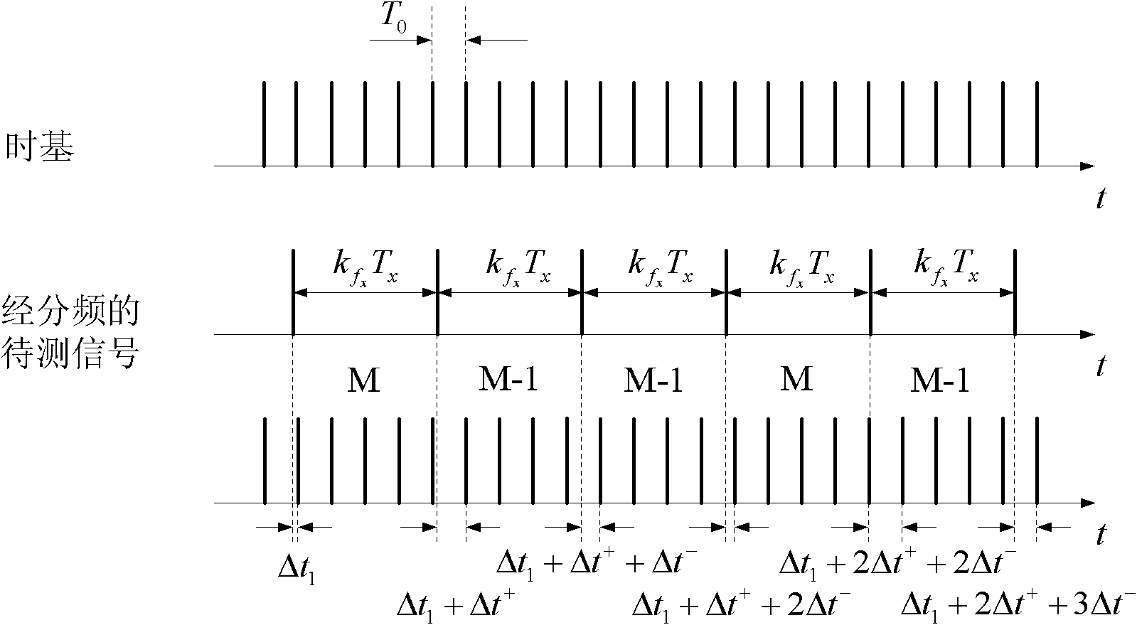

Image

  • High-resolution frequency measurement method with continuous counting interval marking
  • High-resolution frequency measurement method with continuous counting interval marking
  • High-resolution frequency measurement method with continuous counting interval marking

Examples


Embodiment Construction

[0084] Embodiments of the present invention will be described in further detail below in conjunction with the accompanying drawings.

[0085] A high-resolution frequency measurement method for continuously counting interval marks is in the figure 1 The frequency measurement circuit shown is implemented. The frequency measuring circuit is composed of a controller, a frequency divider and two counters connected, and the frequency is f 0 The reference clock is connected to the clock terminals C1 and C2 of counter 1 and counter 2 at the same time, and the frequency is f x The signal to be tested outputs two signals Q and Q with a phase difference of 180° after passing through the frequency divider. An interrupt port, which interrupts the controller at the rising and falling edges of Q, and provides the status of the counter; the two counters are connected to the controller through the bus. The control terminal of the controller is connected with the frequency divider through th...


PUM


Abstract

The invention relates to a high-resolution frequency measurement method with continuous counting interval marking, which is mainly technically characterized by: (1) obtaining data which is continuous on time in measurement time, and constructing measurement arrays of M1, M2, M3...Mn; (2) carrying out judgment and data correction on each data and arrangement way in the measurement arrays; (3) determining the value-taking range of relationship factor and the value; and (4) calculating the frequency to be measured and measuring the resolution. The high-resolution frequency measurement method has reasonable design, and can carry out judgment and correction on the data in the measurement arrays according to the specific rules, reduce output risk produced by input competition and counting errors caused by metastable state of a trigger, simultaneously fully utilize frequency information contained in mutual correlation of the measurement data, realize that the measured resolution is unrelated with signal frequency to be measured, improve the measured resolution, reduce the measurement time and reduce the measurement errors caused by the change of the signal frequency to be measured during the measurement process.

Description

technical field [0001] The invention belongs to the field of signal processing, in particular to a high-resolution frequency measurement method for continuously counting interval marks. Background technique [0002] High-resolution measurement is the basis of high-precision frequency measurement, which is mainly determined by the measurement method. At present, the frequency measurement method mainly adopts the electronic counting method, which has gone through four generations of direct counting method, indirect counting method, interpolation method, and continuous sampling time marking method. (1) Direct counting method: use the known time as the control gate to count the frequency to be measured, and calculate the frequency value to be measured according to the count value, which is the first generation of frequency measurement method used in the 1970s and before. Since only one AND gate and a counter can be used to form a measurement circuit, the circuit is simple and r...

Claims


Application Information

Patent Timeline
IPC IPC(8): G01R23/10
Inventor 张伟玉董晋峰
Owner TIANJIN AGRICULTURE COLLEGE
Learn More