Machining center PLC integration method

A machining center and function technology, applied in the direction of instruments, computer control, simulators, etc., can solve the problems of increased program steps, integrated design, debugging and maintenance difficulties, etc., and achieve the effect of saving scanning time and shortening execution cycle.

Inactive Publication Date: 2010-09-01
宁波恒威机械有限公司
View PDF5 Cites 8 Cited by
  • Summary
  • Abstract
  • Description
  • Claims
  • Application Information

AI Technical Summary

Problems solved by technology

[0002] At present, the logical control programming methods of most CNC machine tool manufacturers for their products are basically based on the characteristics of the controlled objects to compile sequential programs that meet their control requirements one by one, which will greatly increase the number of program steps, which is not conducive to real-time control
There are also a small number of designers who make relatively independent program blocks with the same function and different logic in a small range. This program block can be called unlimited times, which is an improvement over the previous one. However, different input and output interfaces correspond to different PLCs. version, making debugging and maintenance more difficult
However, as a specific logic control of a machining center, no one has designed its logic with PLC logic integration to quickly switch between different interfaces and solve the problem of quick debugging.

Method used


Image

  • Machining center PLC integration method
  • Machining center PLC integration method
  • Machining center PLC integration method

Examples


Embodiment Construction

[0021] Below in conjunction with accompanying drawing and embodiment the present invention will be further described:

[0022] figure 1 Shown, the system that the present invention adopts comprises following unit:

[0023] The input and output filter processing module 1 completely and uniquely maps the physical addresses therein to the internal memory 5 , while the addresses of the other functional modules use all external input and output mappings of the internal memory 5 .

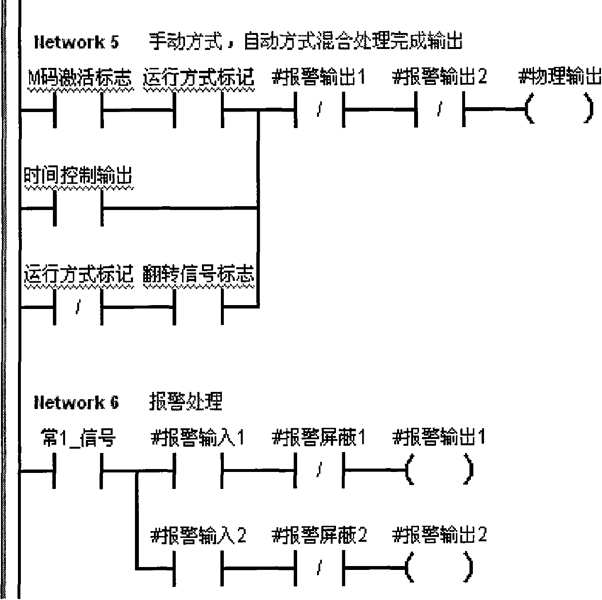
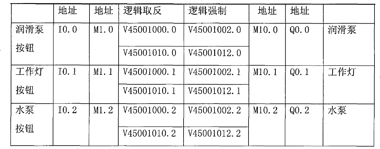
[0024] The input and output logic processing module 2 precisely processes the positive and negative logic and forced logic of the physical address, and is connected with the internal memory 5 through the PLC parameter setting module 6 .

[0025] The function selection module 3 is used for the definition of each local variable in the program control and manual control mixed programming module 4, and will generate the calling of the variable quantity and form of the function module when the function is ca...


PUM


Abstract

The invention relates to a machining center PLC integration method. A function selection module is connected with an input and output filtering processing module, an input and output logic processing module and an internal memory, and controls program contents in a form of byte with the input and output filtering processing module, the input and output logic processing module and the internal memory so as to form a machining center PLC integration system capable of realizing module functions according to needs of the outside. The machining center PLC integration method has the advantages of completely and uniquely mapping physical addresses into the internal memory in the input and output filtering processing module, precisely processing the positive negative logic and forced logic of the physical addresses in the input and output logic processing module, saving scanning time and shortening execution period; and a program control and manual control mixed programming module is a main part of an entire PLC, and the art of programming of the program control and manual control mixed programming module is directly related to the level of integration and also determines the compactness and intensiveness of the logic of the entire PLC.

Description

technical field [0001] The invention belongs to the field of numerical control machining centers and motion control, and mainly relates to a PLC integration method of a machining center. Background technique [0002] At present, the logical control programming methods of most CNC machine tool manufacturers for their products are basically based on the characteristics of the controlled objects to compile sequential programs that meet their control requirements one by one, which will greatly increase the number of program steps, which is not conducive to real-time control. There are also a small number of designers who make relatively independent program blocks with the same function and different logic in a small range. This program block can be called unlimited times, which is an improvement over the previous one. However, different input and output interfaces correspond to different PLCs. version, making debugging and maintenance more difficult. However, as a specific log...

Claims


Application Information

Patent Timeline
IPC IPC(8): G05B19/4093
Inventor 张军宁崔怀芳
Owner 宁波恒威机械有限公司
Why Eureka
Try Eureka