System debugging method for DC ice melting device

A technology of DC ice melting and debugging method, which is applied to measurement devices, program control devices, software testing/debugging, etc., can solve the problems of transmission lines threatening the safe operation of power systems, etc., and achieve the effect of reliable operation.

Active Publication Date: 2010-09-01
ELECTRIC POWER RESEARCH INSTITUTE, CHINA SOUTHERN POWER GRID CO LTD
View PDF3 Cites 16 Cited by
  • Summary
  • Abstract
  • Description
  • Claims
  • Application Information

AI Technical Summary

Problems solved by technology

[0002] Icing of existing transmission lines in winter se

Method used


Image

  • System debugging method for DC ice melting device
  • System debugging method for DC ice melting device
  • System debugging method for DC ice melting device

Examples


Embodiment 1

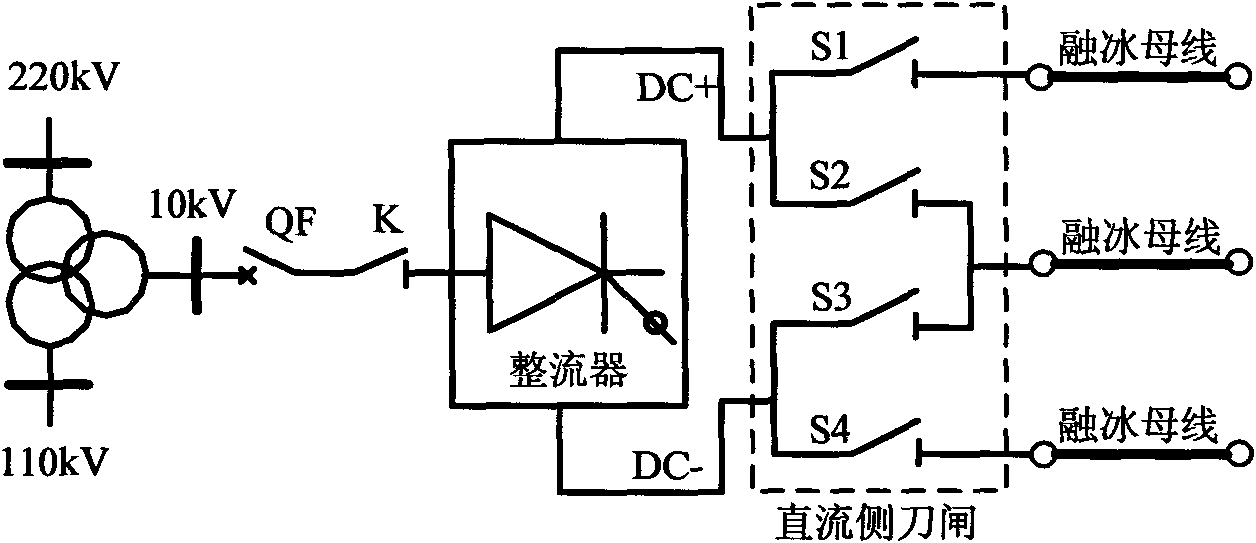
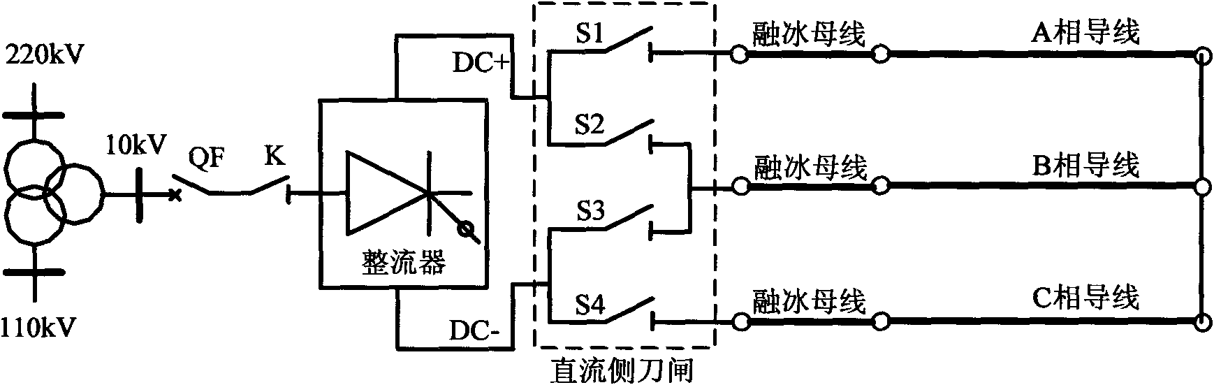
[0049] For the system commissioning schematic diagram of DC ice melting device without special rectifier transformer, see figure 1 and figure 2 . (1) Combined with the DC deicing device, use the substation to analyze and calculate the voltage level and system stability of various commissioning conditions by using the electromechanical transient simulation program, and formulate the accident plan. In the electromagnetic transient simulation program, an equivalent power supply model including the detailed control and protection functions of the DC deicing device is established, and the start-stop sequence of the DC deicing device, the filter switching strategy, control and protection functions and parameters, and the conversion of working conditions are tested, and The harmonics and reactive power of the DC deicing device under various working conditions are analyzed. (2) figure 1 In the process, the DC side knife switches S1, S2, S3 and S4 are kept disconnected, and the swi...

Embodiment 2

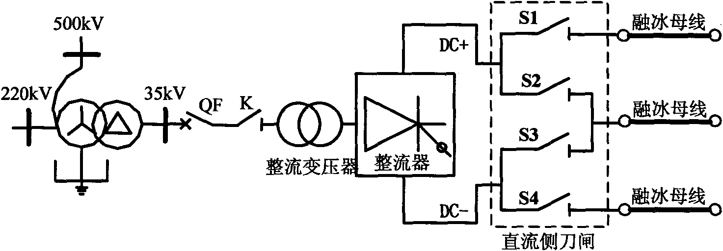
[0051] For the system commissioning diagram of the DC ice-melting device with a special rectifier transformer, see image 3 and Figure 4 . (1) Combined with the DC deicing device, use the substation to analyze and calculate the voltage level and system stability of various commissioning conditions by using the electromechanical transient simulation program, and formulate the accident plan. In the electromagnetic transient simulation program, an equivalent power supply model including the detailed control and protection functions of the DC deicing device is established, and the start-stop sequence of the DC deicing device, the filter switching strategy, control and protection functions and parameters, and the conversion of working conditions are tested, and The harmonics and reactive power of the DC deicing device under various working conditions are analyzed. (2) image 3 In the process, the DC side switch S1, S2, S3 and S4 are disconnected, the switch K is closed and then...


PUM


Abstract

The invention discloses a system debugging method for a DC ice melting device. The method comprises the following steps of: 1) analyzing and calculating the system under a debugging condition and performing an analog simulation test; 2) performing a closing impact test on the DC ice melting device; 3) performing an open-circuit test without an ice melting bus; 4) performing an open-circuit test with the ice melting bus; 5) performing an unlocking and blocking test with an ice melting circuit; 6) performing a manual emergency shutdown test with load; and 7) performing a heavy current test withthe ice melting circuit. The method can ensure thorough detection of the function and performance of the DC ice melting device through the system debugging and ensure that the DC ice melting deice can be reliably put into operation when needing ice melting. The method is a convenient and practical system debugging method for the DC ice melting device.

Description

technical field [0001] The invention is a system debugging method of a direct current ice melting device, which belongs to the innovative technology of the system debugging method of a direct current ice melting device. Background technique [0002] Icing of existing transmission lines in winter seriously threatens the safe operation of the power system. The successful development of the DC ice melting device has played a huge role in improving the power grid's ability to resist ice disasters. The basic principle of the DC ice-melting device is to use a converter valve to convert the AC current into a DC current, inject it into the AC wire, and use the DC current to generate heat in the wire resistance to melt the ice. Due to the task of power transmission, the transmission line can be stopped and connected to the ice-melting device for debugging for a short time. A simple, efficient, systematic and comprehensive system debugging method is an important guarantee for the DC...

Claims


Application Information

Patent Timeline
IPC IPC(8): H02G7/16G01R31/00G06F11/36G06F9/455
Inventor 傅闯黎小林饶宏许树楷赵杰李立浧吴怡敏
Owner ELECTRIC POWER RESEARCH INSTITUTE, CHINA SOUTHERN POWER GRID CO LTD
Why Eureka
Try Eureka