

Automatic correction circuit and method of capacitor
An automatic correction and capacitance technology, applied in the direction of electrical components, electrical signal transmission systems, networks using active components, etc., can solve the problems of dynamic nonlinear error expansion and correction errors of analog-to-digital converters
- Summary
- Abstract
- Description
- Claims
- Application Information
AI Technical Summary
Problems solved by technology
Method used
Image

Examples
no. 1 example
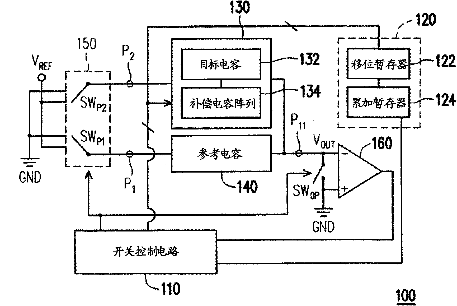
[0039] Please refer to figure 1 Shown is a schematic diagram of an automatic correction circuit for capacitance according to the first embodiment of the present invention. The automatic calibration circuit 100 of the first embodiment of the present invention includes a switch control circuit 110, a counting unit 120, a capacitor array 130, a reference capacitor 140, a switch group 150, a comparator 160 and a switch SW OP .
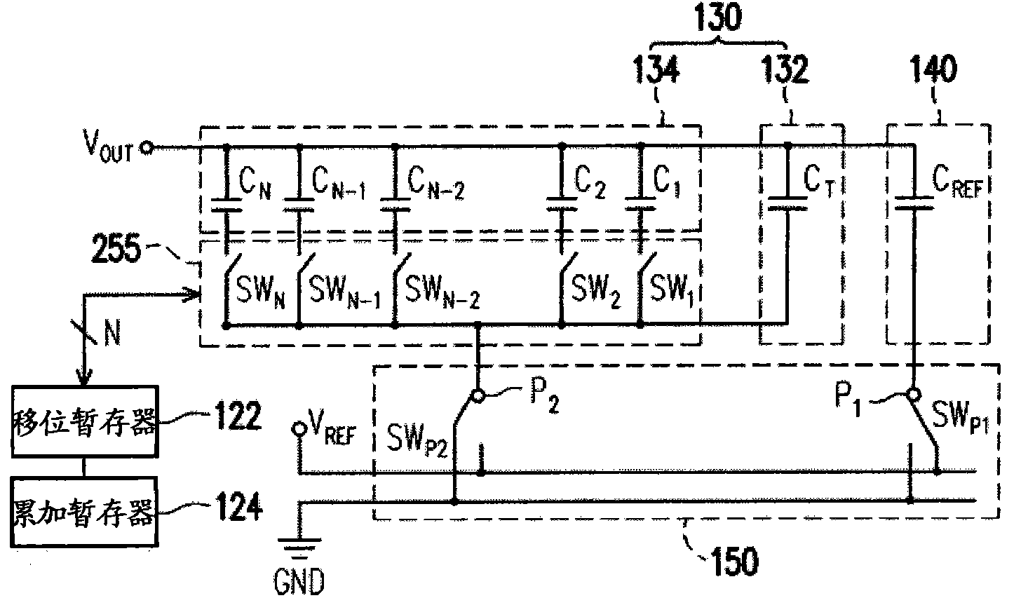
[0040] The above-mentioned capacitor array 130 also includes a target capacitor 132 and a compensation capacitor array 134 , wherein the compensation capacitor array 134 has a plurality of compensation capacitors (not shown), which can be used to connect the target capacitor 132 in parallel to adjust the capacitance value of the capacitor array 130 .
[0041] One end of the aforementioned reference capacitor 140 is coupled to the common end P 11 , the other end is coupled to the first input terminal P 1 ; One end of the target capacitor 132 is coupled t...
no. 2 example
[0059] image 3 For the progressive analog-to-digital converter according to the second embodiment of the present invention, the analog-to-digital converter 300 includes a shift register 322, an accumulation register 324, a switch control circuit 310, a switch group 350, a comparator 360, a reference capacitor C REF And capacitor arrays 331, 332. The shift register 322 and the accumulation register 324 are coupled between the switch control circuit 310 and the capacitor arrays 331 and 332, and the switch control circuit 310 is also coupled to the switch group 350 and the switch group 355 to control the switch. The switch bank 350 includes switches SW 31 、SW 32 、SW 33 , one end of which is respectively coupled to the first input end P 1 , the second input terminal P 2 with the third input P 3 , the other end is switchably coupled to the input voltage V IN , reference voltage V REF Or ground terminal GND. first input terminal P 1 , the second input terminal P 2 with...
no. 3 example
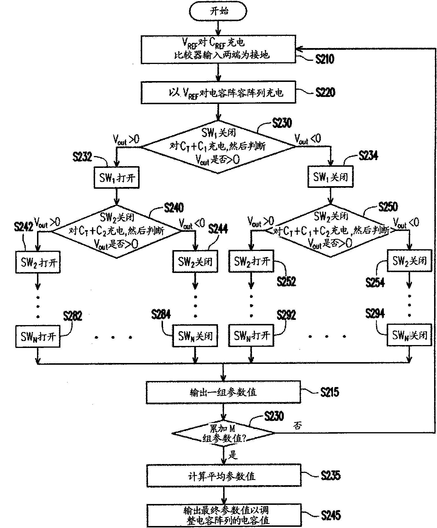
[0063] From another point of view, the present invention proposes a method for automatically calibrating capacitance, using multiple automatic calibrating procedures to reduce errors in the calibrating process, please refer to Figure 4 , Figure 4It is a flow chart of the method for automatically calibrating capacitance according to the third embodiment of the present invention. First, compare the capacitance values of the capacitor array and the reference capacitor to output a set of parameter values (step S410), and then adjust the parallel relationship between the compensation capacitor and the target capacitor according to the parameter values to adjust the capacitance value of the capacitor array (step S420). Next, the above steps S410, S420 are repeatedly executed to generate multiple sets of parameter values (step S430), and then the above parameter values are accumulated and the average value of the above parameter values is calculated to output a final pa...
PUM
 Abstract
Description
Claims
Application Information