Magnesium alloy hot-rolling mill

A magnesium alloy and rolling mill technology, applied in metal rolling, metal rolling, metal processing equipment, etc., can solve problems such as low yield rate, inability to become coil material, and inability to increase production volume, so as to ensure quality and prevent Effect of temperature fluctuation and improvement of yield

Inactive Publication Date: 2010-09-01
IHI CORP
View PDF3 Cites 22 Cited by
  • Summary
  • Abstract
  • Description
  • Claims
  • Application Information

AI Technical Summary

Problems solved by technology

[0010] However, in the hot rolling devices disclosed in the above-mentioned Patent Document 1 and Patent Document 2, since the coiling portion at the front end of the coil and the tailing portion at the rear end cannot be heated and rolled stably, it cannot be used as a coil material.
In addition, there are disadvantages such as low yield and inability to increase production volume.

Method used


Image

  • Magnesium alloy hot-rolling mill
  • Magnesium alloy hot-rolling mill
  • Magnesium alloy hot-rolling mill

Examples


Embodiment Construction

[0036] Hereinafter, an embodiment of the present invention will be described with reference to the drawings.

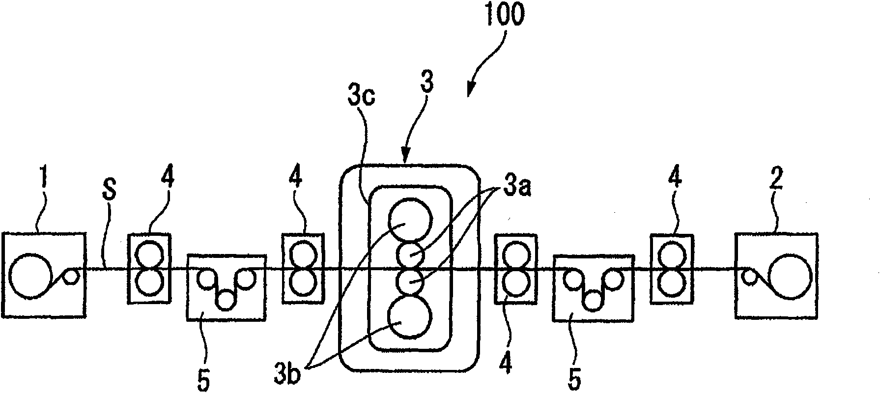
[0037] figure 1 It is a front view showing the structure of the hot rolling apparatus 100 in this embodiment.

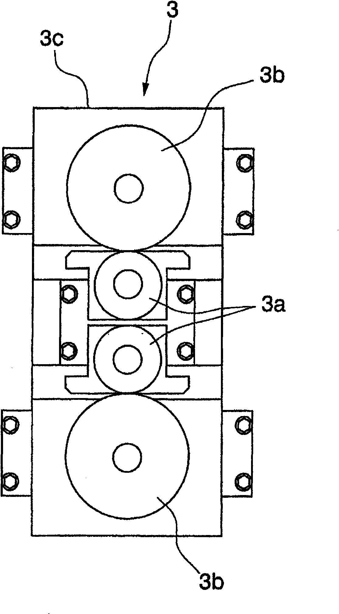
[0038] Such as figure 1 As shown, the hot-rolling device 100 (magnesium alloy hot-rolling device) according to this embodiment includes a first holding coiler 1 (coiler), a second holding coiler 2 (coiler), and a rolling mill. 3. A plurality of pairs of pinch rollers 4, and a tension adjustment device 5.

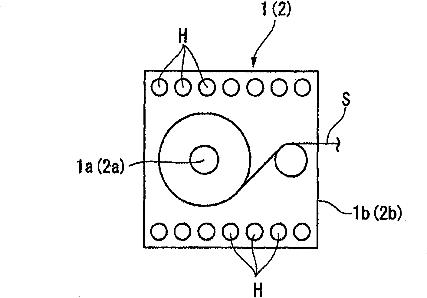
[0039] figure 2 It is a schematic diagram which shows the schematic structure of the 1st holding|maintenance heating coiler 1 and the 2nd holding|maintenance heating coiler 2.

[0040] The two-hold heating coilers 1 and 2 include coiling sections 1a and 2a and holding furnaces 1b and 2b. A heater H is built in the holding furnaces 1b and 2b.

[0041] This holding heating coiler 1,2 is arranged at both ends of the inlet side and the outlet side of th...


PUM

PropertyMeasurementUnit
thicknessaaaaaaaaaa
thicknessaaaaaaaaaa
thicknessaaaaaaaaaa

Abstract

A magnesium alloy hot-rolling mill (100), in which winders (1, 2) capable of heating and heat-retaining a magnesium alloy sheet (S) in a coiled state are installed at both input and output sides of a rolling machine (3), and the magnesium alloy sheet is sequentially pressed by multiple reverse rolling operations to gradually reduce the thickness of the sheet. The rolling machine (3) has work rolls (3a) each having a surface heatable to a predetermined temperature and also has backup rolls (3b). With the mill, degradation of the quality of products due to a temperature change during hot rolling of a magnesium alloy can be prevented, the yield of the products can be increased, and the amount of production of the products can be increased.

Description

technical field [0001] The invention relates to a magnesium alloy hot rolling device. [0002] This application claims the priority of Japanese Patent Application No. 2007-269057 for which it applied in Japan on October 16, 2007, and uses the content here. Background technique [0003] In order to produce a magnesium alloy sheet, for example, a round bar-shaped blank with a diameter of 300 to 400 mm and a length of 500 to 600 mm is formed into a thick plate with a thickness of 10 mm or less by hot extrusion, and the thick plate is cut into a predetermined length. (for example, 3 m) is used as a cut plate material, and the above cut plate material is rolled to a thickness of about 1 mm by rough rolling. [0004] Then, the magnesium alloy coil with a thickness of about 1 mm is further rolled by finish rolling to produce a coil material with a thickness in the range of 0.2 to 0.5 mm or a coil with a thickness of 50 μm or less (for example, 30 to 40 μm). [0005] Since magnesi...

Claims


Application Information

Patent Timeline
Patent Type & Authority Applications(China)
IPC IPC(8): B21B1/32B21B3/00B21C47/00
CPCB21B39/006B21B1/34B21C47/26B21C47/00B21B3/00B21B2027/086
Inventor 田添信广本城恒松村英夫箭内胜彦箭内良行
Owner IHI CORP
Why Eureka
Try Eureka