Method and die carrier for forging and molding special-shaped cross section metal blank with through holes

A special-shaped cross-section and metal technology, which is applied in the field of forging, can solve the problems of material consumption and machining workload, large machining workload, and large material consumption, so as to achieve the effect of ensuring various dimensions and technical requirements and satisfying reasonable connection

Inactive Publication Date: 2010-09-08
INNER MONGOLIA FIRST MACHINERY GRP
View PDF6 Cites 9 Cited by
  • Summary
  • Abstract
  • Description
  • Claims
  • Application Information

AI Technical Summary

Problems solved by technology

Most of the blanks currently used for this part are open die forgings. The shape of the forgings has a certain forging slope. The extrusion method only extrudes the outer contour (the inner hole and the flat groove are not formed, and they are still completed by machining), and the material consumption and machining workload are also relatively large; in recent years, there have also been researches on the method of warm extrusion forming. Although the inner and outer contours are formed, it needs 4 sets of pressure equipment, and it can be completed through multiple processes such as billet making, pre-forming, extrusion, punching, and shaping, and has not been used in production.

Method used


Image

  • Method and die carrier for forging and molding special-shaped cross section metal blank with through holes
  • Method and die carrier for forging and molding special-shaped cross section metal blank with through holes
  • Method and die carrier for forging and molding special-shaped cross section metal blank with through holes

Examples


Embodiment

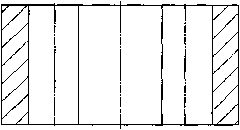
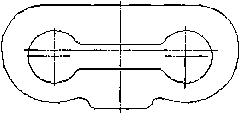
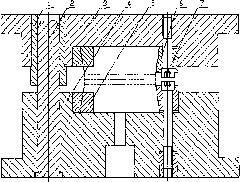
[0016] With reference to the attached figure 1 , 2 It is the end coupler part to be processed. Formwork (attached image 3 As shown) the structure is that the guide sleeve 1 and the guide post 2 are assembled on the upper mold base 3 and the lower mold base 4 respectively, so as to ensure the precise guidance of the upper mold base and the lower mold base during work. Area A 19, Area B 20, and Area C 21 are the mold loading positions of the three stations on the mold base. They are respectively equipped with specific molds for billet making, extrusion forming, and punching and continuous skin. The installation angle of the mold is ensured by the key block 5 and the lateral positioning of the mold base, and the mold base is fastened together by the pressure plate 6 and the screw 7. In the three strokes of the slider of the pressure equipment, the blank passes through the A zone 19 and the B zone respectively. The three-station mold in zone 20 and zone C 21 completes the work...


PUM


Abstract

The invention relates to a method and a die carrier for forging and molding a special-shaped cross section metal blank with through holes. The molding method comprises that: three die setting stations are arranged on a set of die carrier and are provided with specific dies for preforming, extrusion molding and wad punching respectively; and the blank passes through the dies of the three stations respectively in three strokes of a sliding block of pressure equipment, and the pressure equipment performs the preforming, extrusion molding and wad punching so as to finish the whole molding process of the work piece. The method and the die carrier have the advantages of finishing the whole molding machining process of a forge piece on one piece of pressure equipment by adopting the machining processes of preforming, extrusion molding and wad punching, and meeting the objective requirements of a design process and actual operation because the three-station die carrier structure with an independent clamping function and a die offset adjustment function is arranged on the tool structure.

Description

technical field [0001] The invention relates to a forging forming method and a mold base of a metal with a special-shaped cross-section with a through hole, in particular to a hot extrusion and closed forging forming method and a mold base of a metal with a special-shaped cross-section, belonging to the field of forging. Background technique [0002] Extrusion and closed forging have been widely used as a method of metal forging, and the forming process is different according to the structure and requirements of each workpiece. For example: the end coupler part is a part with special-shaped inner and outer contours, and the inner and outer contours are not concentric. There are strict requirements on the inner and outer dimensions of the part. Most of the blanks currently used for this part are open die forgings. The shape of the forgings has a certain forging slope. The extrusion method only extrudes the outer contour (the inner hole and the flat groove are not formed, and...

Claims


Application Information

Patent Timeline
Patent Type & Authority Applications(China)
IPC IPC(8): B21J5/06B21J13/02
Inventor 王海旺宫显宇祝占宏王志国林海马涛高扬陈海鹏谷志飞
Owner INNER MONGOLIA FIRST MACHINERY GRP
Why Eureka
Try Eureka