
Combined lathe

A combined lathe and horizontal carriage technology, applied in the field of machinery, can solve the problems of inability to reduce production costs and low production efficiency, and achieve the effects of simple structure, high processing efficiency and flexible processing parts

Inactive Publication Date: 2013-11-06
玉环县清港海飞机床厂
View PDF1 Cites 0 Cited by
  • Summary
  • Abstract
  • Description
  • Claims
  • Application Information

AI Technical Summary

Problems solved by technology

This kind of lathe is mainly operated by workers manually, and the production efficiency is low. It is suitable for single-piece, small-batch production and repair workshops.
If it is necessary to process the valve stem seat of the valve body, the steps of drilling, tapping and drawing the inner groove must be carried out in sequence. Due to the wide application of valves and the large production and sales volume, it is obvious that ordinary lathe processing cannot meet the production needs.
[0003] For this reason, in order to improve production efficiency and reduce production costs, some people use CNC lathes for production, and even design a set of assembly lines for production, but there are still problems that cannot reduce production costs.

Method used


Image

  • Combined lathe
  • Combined lathe

Examples


Embodiment Construction

[0021] The following are specific embodiments of the present invention and in conjunction with the accompanying drawings, the technical solutions of the present invention are further described, but the present invention is not limited to these embodiments.

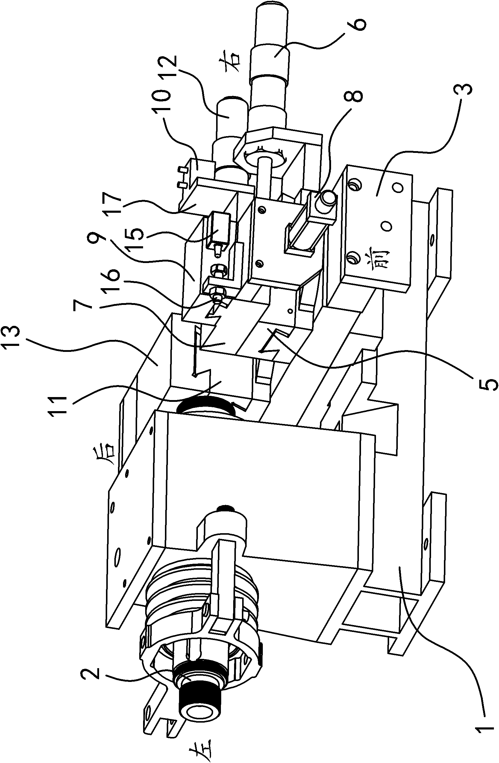
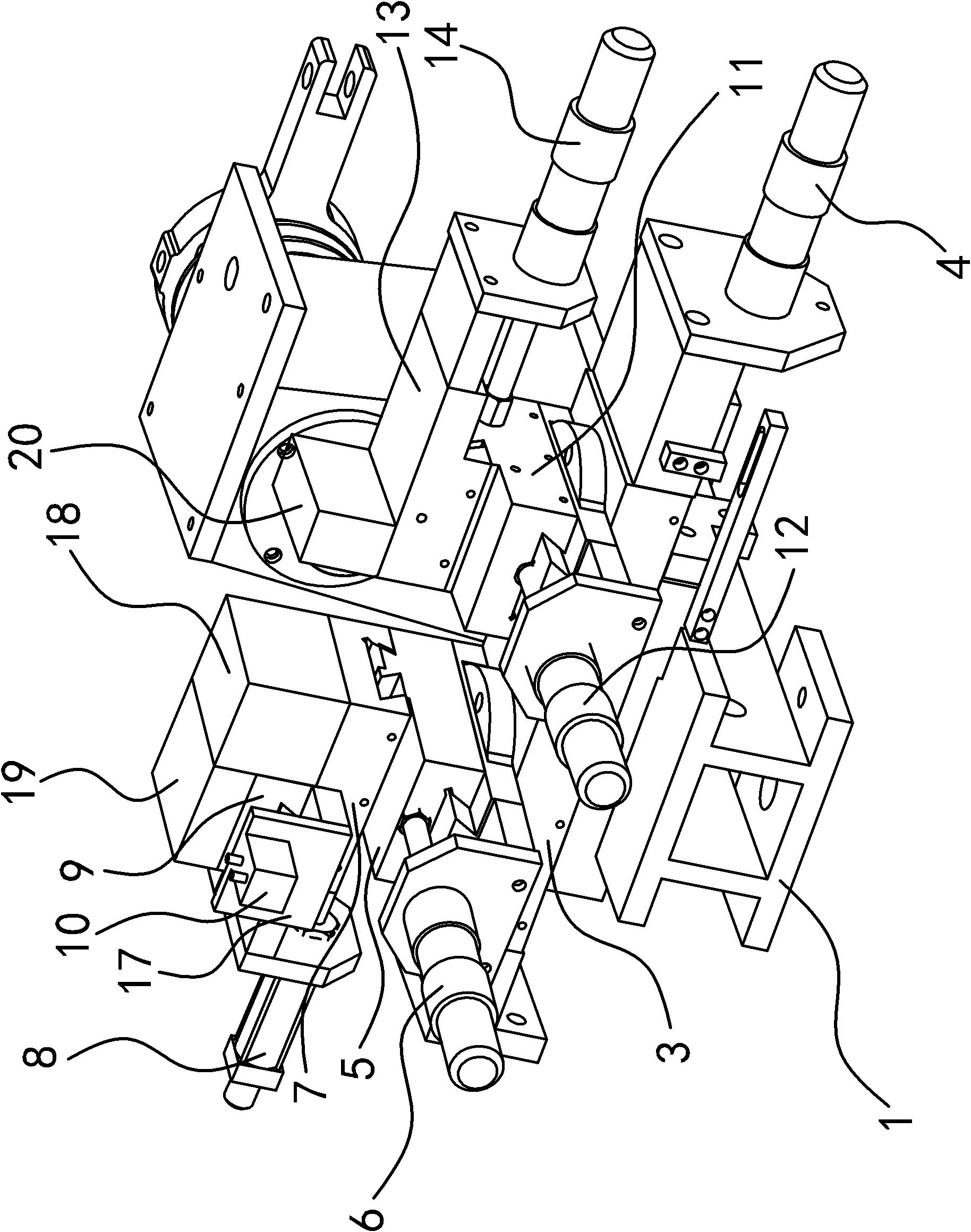
[0022] Such as figure 1 and figure 2 As shown, the combined lathe includes a machine base 1, a main shaft 2, a fixture, a carriage, a driving mechanism, and a tool holder.

[0023] Specifically, the main shaft 2 is installed on the base 1 and a clamp for clamping the workpiece is provided at the front end of the main shaft 2 , and a motor for driving the main shaft 2 is provided on the base 1 .

[0024] Such as figure 1 As shown, the front side, the rear side, the left side and the right side are auxiliary defined in the accompanying drawings. On the right side of the clamp, there is a horizontal carriage one 3 perpendicular to the axis of the main shaft 2, and the horizontal carriage one 3 is fixed on the base 1 and c...


PUM


Abstract

The invention provides a combined lathe, which belongs to the technical field of machinery. The invention solves the problems that the existing lathe has low production efficiency, and can not meet the valve production requirements. The combined lathe comprises a machine seat, a main shaft, a motor, a clamp, a first transverse dragging plate and a first driving mechanism, wherein a first vertical dragging plate and a third vertical dragging plate capable of horizontally sliding in the direction parallel to the axial line direction of the main shaft are arranged in parallel on the first transverse dragging plate, a sixth driving mechanism capable of making the first vertical dragging plate slide and an eighth driving mechanism capable of making the third vertical dragging plate slide are arranged on the first transverse dragging plate, a first cutter frame capable of fixing a first cutter is arranged on the first vertical dragging plate, and a third cutter frame capable of fixing a third cutter is arranged on the third vertical dragging plate. Each cutter of the combined lathe can sequentially process a valve body, the batch processing requirement can be met, at the same time, the cutter conversion speed is high, and the production efficiency is improved. The combined lathe also has the advantages of reasonable layout, simple structure and high part processing efficiency.

Description

technical field [0001] The invention belongs to the technical field of machinery, and relates to a lathe, in particular to a combination lathe. Background technique [0002] A lathe is a machine tool that mainly uses a turning tool to turn a rotating workpiece. Drills, reamers, reamers, taps, dies and knurling tools can also be used for corresponding processing on the lathe. Ordinary lathes have a wide range of processing objects, and the adjustment range of the spindle speed and feed rate is large. It can process the inner and outer surfaces, end faces and internal and external threads of the workpiece. The tool is installed on the turret, and the turret is rotated according to different processing requirements. This kind of lathe is mainly operated by workers manually, and the production efficiency is low. It is suitable for single-piece, small-batch production and repair workshops. If it is necessary to process the valve stem seat of the valve body, the steps of drillin...

Claims


Application Information

Patent Timeline
Patent Type & Authority Patents(China)
IPC IPC(8): B23B11/00
Inventor 熊远飞彭君海
Owner 玉环县清港海飞机床厂
Learn More