Optical module heat-dissipation structure

A heat dissipation structure and optical module technology, applied in the field of optical communication, can solve the problems of neglecting the heat dissipation of the optical module, difficult insertion and removal of the optical module, and large compression force of the thermal pad, so as to improve the overall heat dissipation effect, improve the heat dissipation effect, and increase the heat conduction area. and the effect of heat dissipation area

Inactive Publication Date: 2019-10-15
武汉永信丰科技有限公司
View PDF11 Cites 8 Cited by
  • Summary
  • Abstract
  • Description
  • Claims
  • Application Information

AI Technical Summary

Problems solved by technology

However, this type of heat dissipation structure often ignores the full range of heat dissipation for the optical module. In addition to considering heat dissipation on the upper surface of the optical module, it is also necessary to consider heat dissipation on other surfaces, which has the prob...

Method used


Image

  • Optical module heat-dissipation structure
  • Optical module heat-dissipation structure
  • Optical module heat-dissipation structure

Examples


Embodiment 1

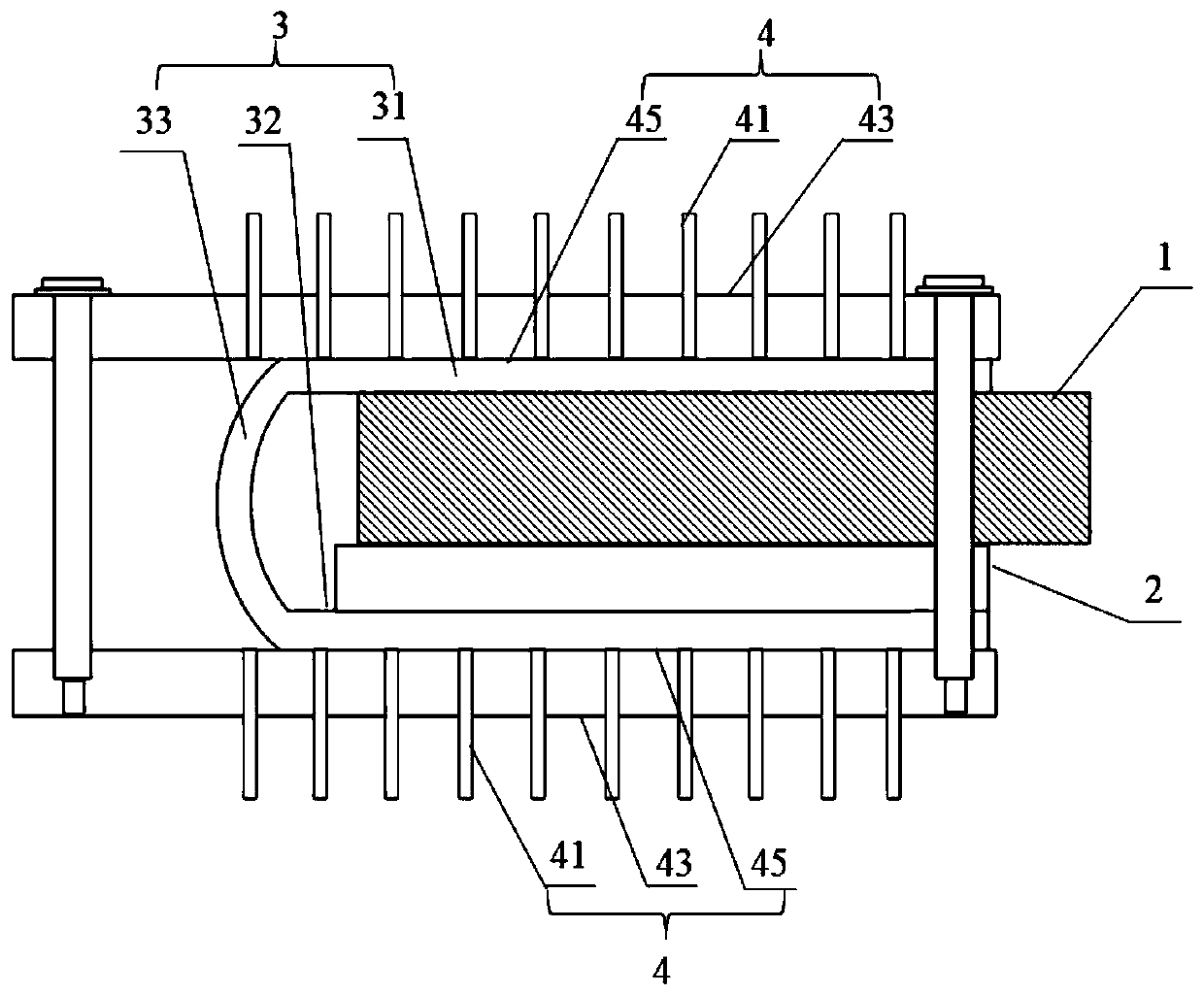
[0045] Embodiment one, as figure 1 As shown, a heat dissipation structure of an optical module includes a flexible printed circuit board 2 and a flexible heat conducting member 3;

[0046] The flexible heat conducting member 3 includes a first fixing portion 31 , a second fixing portion 32 and a bending portion 33 , the inside of the first fixing portion 31 is opposite to the inside of the second fixing portion 32 , and the first fixing portion 32 is opposite to the inside of the second fixing portion 32 . part 31 and the second fixing part 32 are connected together through the bending part 33; the flexible printed circuit board 2 is fixedly arranged on the inner side of the second fixing part 32; at least one optical module 1 is pluggable disposed between the inner side of the first fixing portion 31 and the flexible printed circuit board 2;

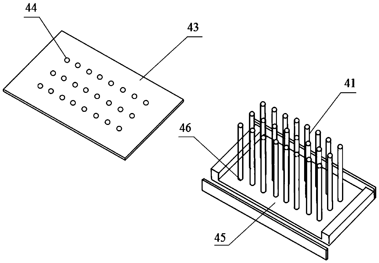
[0047] A cooling element 4 is respectively fixed on the outer sides of the first fixing portion 31 and the second fixing portion 32 ....

Embodiment 2

[0056] Embodiment two, such as image 3 As shown, an optical module heat dissipation structure, on the basis of the first embodiment, the heat dissipation element 4 also includes a cooling pipe 42 filled with cooling liquid, and the cooling pipe 42 is laid on the first surface 42 and the second surface In the inner space enclosed by the surface 45 .

[0057] In this embodiment, in addition to improving the heat dissipation effect through the heat dissipation function of the first through hole, the second through hole and the capillary heat dissipation pipe, the heat transferred to the first surface of the heat dissipation element can be cooled in time through the cooling pipe filled with cooling liquid. down, thereby reducing the excessive temperature in the optical module, ensuring the normal operation of the optical module, and further effectively improving the heat dissipation effect; at the same time, when the optical module is inserted between the inner side of the first ...

Embodiment 3

[0064] Embodiment three, as Figure 5 As shown, an optical module heat dissipation structure, on the basis of Embodiment 1 and Embodiment 2, also includes an air control heat dissipation device 5 for controlling heat dissipation through a fan, and the air control heat dissipation device 5 includes a bracket 57, the The air control cooling device 5 is fixed between the two heat sinks 4 through the bracket 57 , and the two ends of the bracket 57 protrude out of the first surfaces 43 of the two heat sinks 4 respectively.

[0065] The heat emitted by the two heat sinks can be disseminated to the peripheral space in time through the wind control heat dissipation device, and the overall heat dissipation effect of the optical module can be further improved through the double heat dissipation function formed by the heat sink; at the same time, when the optical module is inserted into the When the inner side of the first fixing part is between the flexible printed circuit board, due to...


PUM


Abstract

The invention relates to an optical module heat-dissipation structure. The optical module heat-dissipation structure comprises a flexible printed circuit board and a flexible heat conduction part, wherein the flexible heat conduction part comprises a first fixing part, a second fixing art and a bending part; an inner side of the first fixing part and an inner side of the second fixing part are opposite to each other; the first fixing part and the second fixing part are connected together through the bending part; the flexible printed circuit board is fixedly arranged on the inner side of the second fixing part; at least one optical module is arranged between the inner side of the first fixing part and the flexible printed circuit board in a pluggable way; and a heat-dissipation part are fixedly arranged on outer sides of the first fixing part and the second fixing part respectively. The optical module heat-dissipation structure is simple, improves the overall heat-dissipation effect remarkably, enables a temperature-sensitive laser in the optical module to work smoothly, and is easy to plug and unplug, convenient to use, and suitable for generalization.

Description

technical field [0001] The invention relates to the technical field of optical communication, in particular to an optical module heat dissipation structure. Background technique [0002] An optical module is an integrated module that converts optical signals into electrical signals and / or converts electrical signals into optical signals. It is usually mounted on a printed circuit board and plays an important role in optical fiber communication in the communication field. . With the rapid development of 4G communication and even 5G communication, the market demand for high-speed optical modules is increasing day by day. [0003] However, during the working process of the optical module, a large amount of heat will be generated. The laser in the optical module is the most important power consumption device in the optical module, especially the laser for generating optical signals, which generates the most heat. Taking the 100G optical module as an example, its power consumpt...

Claims


Application Information

Patent Timeline
IPC IPC(8): G02B6/42
CPCG02B6/4268G02B6/4269
Inventor 向文锋刘绚
Owner 武汉永信丰科技有限公司
Why Eureka
Try Eureka