Multi-cavity steel tube concrete superposed column and preparation method thereof

A technology of concrete-filled steel pipe columns and concrete-filled steel pipes, which is applied in the direction of columns, pier columns, pillars, etc., can solve the problems of weakening the advantages of steel pipe concrete inner columns, reducing the bearing capacity of steel pipe concrete composite columns, and reducing the useable area of ​​buildings, etc., to achieve The building functions are fully reasonable, the space utilization rate is improved, and the effect of earthquake resistance is improved

Active Publication Date: 2010-09-08
BEIJING UNIV OF TECH
View PDF6 Cites 15 Cited by
  • Summary
  • Abstract
  • Description
  • Claims
  • Application Information

AI Technical Summary

Problems solved by technology

[0003] However, the use of concrete-filled steel tube composite columns in super high-rise buildings is not widely used. One of the reasons is that super high-rise buildings often require huge columns to bear huge loads. To increase the size of the section reduces the usable area of ​​t

Method used


Image

  • Multi-cavity steel tube concrete superposed column and preparation method thereof
  • Multi-cavity steel tube concrete superposed column and preparation method thereof
  • Multi-cavity steel tube concrete superposed column and preparation method thereof

Examples


Embodiment 1

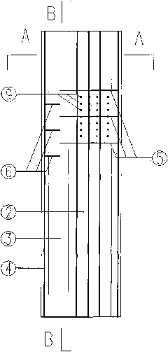
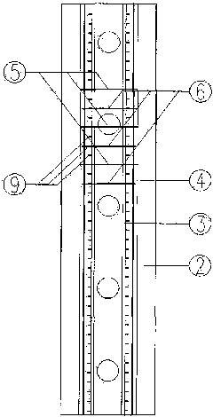
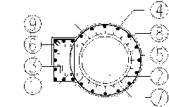
[0032] Schematic diagram of structural steel and reinforcement in a multi-cavity steel tube concrete composite column whose cross-section shape is a table tennis racket Figure 1 ~ Figure 3 shown. In this embodiment, a multi-cavity steel pipe 1 composed of a steel pipe 2 and a steel plate 3 is combined with poured concrete and a reinforced concrete outer column 8. The two strip-shaped steel plates in this embodiment are welded at a vertical angle to the longitudinal edge. And the third steel plate is welded on the longitudinal side to form a U-shaped groove, and the U-shaped groove is welded to the circular cross-section steel pipe in the longitudinal direction to form the multi-cavity steel pipe 1 in the steel tube concrete inner column. The steel pipe 2 and the steel plate 3 are reserved with holes to facilitate concrete pouring, and the steel plate 3 also has holes for binding hoops. Weld rivets 9 on the outer wall of the multi-cavity steel pipe 1, and then bind the longit...

Embodiment 2

[0043] The structure of this embodiment is basically the same as that of Embodiment 1, the only difference is that the cross-sectional shape of the multi-cavity steel pipe is different, such as Figure 4 ~ Figure 6 As shown, the multi-cavity steel pipe in this embodiment is composed of two strip-shaped steel plates and two steel pipes whose cross-sectional shape is an equilateral right triangle. The two long sides of the two strip-shaped steel plates are respectively welded to the longitudinal right-angled sides and the longitudinal acute-angled sides of the two equilateral right-angled triangular cross-section steel pipes, and the two long sides of the other strip-shaped steel plate are respectively welded to the longitudinal acute-angled sides of the two equilateral right-angled triangular cross-section steel pipes. The sides are welded at right angles to the longitudinal side, and the two strip steel plates are parallel to each other and perpendicular to the steel plates of ...

Embodiment 3

[0045] The structure of this embodiment is basically the same as that of Embodiment 1, the only difference is that the cross-sectional shape of the multi-cavity steel pipe is different, such as Figure 7 ~ Figure 9 As shown, the multi-cavity steel pipe in this embodiment is composed of two strip-shaped steel plates and two steel pipes with the same size and rectangular cross-section shape, and the two long sides of the strip-shaped steel plates are respectively welded to the longitudinal right-angle sides of the two rectangular cross-section steel pipes. , the two long sides of another strip steel plate are respectively welded to the opposite sides of the longitudinal right-angled sides of the two welded rectangular cross-section steel pipes, and the surface formed by the two welded right-angled sides on each rectangular cross-section steel pipe is perpendicular to the two strip steel plates In this way, a multi-cavity steel pipe with a diamond-shaped outer contour is formed. ...


PUM


Abstract

The invention relates to a superposed column, particularly to a multi-cavity steel tube concrete superposed column and a preparation method thereof. The superposed column is prepared by the steps of: welding a steel plate and a steel tube, which are preprocessed with holes, vertically to obtain a multi-cavity steel tube; welding rivets on the external wall of the multi-cavity steel tube; binding a steel mesh formed by longitudinal steel bars and hoops on the outside of the multi-cavity steel tube; and supporting a template and pouring concrete to form the multi-cavity steel tube concrete superposed column, the inside of which is a multi-cavity steel tube concrete column and the outside of which is reinforced concrete. The superposed column solves the disadvantage that the hooping effect is reduced due to an oversize steel tube in a large-sized steel tube concrete superposed column. Moreover, compared with the traditional superposed column, the superposed column has much more flexible and diverse section forms, and thus the functions of a building can be fully utilized and the usable floor area is increased without lowering the carrying capacity of the superposed column.

Description

technical field [0001] The invention relates to a shear wall composite column, in particular to a multi-cavity steel pipe concrete composite column and a manufacturing method thereof. Background technique [0002] With the improvement of people's living standards, residents have higher and higher requirements for residential and office buildings, and high-rise and super high-rise buildings have gradually increased. In the large number of reinforced concrete high-rise buildings, the use of concrete-filled steel tube columns has been widely used. Its structural form not only effectively improves the bearing capacity of the internal concrete, but also overcomes the shortcomings of steel tube structures that are prone to local buckling. The effect of the combination of the two materials is far greater than the simple superposition of the two. However, with the maturity of CFST technology, its shortcomings are becoming more and more obvious. The emergence of CFST composite colu...

Claims


Application Information

Patent Timeline
IPC IPC(8): E04C3/34E04C5/01E04B1/30E04G21/00
Inventor 曹万林彭斌张建伟
Owner BEIJING UNIV OF TECH
Why Eureka
Try Eureka