Side-by-side sound wave throttle valve

A throttle and sound wave technology, which is applied in engine control, machine/engine, mechanical equipment, etc., can solve the problems of insufficient air intake of the engine throttle, short service life of the engine, uneven air intake, etc., so as to save fuel and improve The effect of shortening the power and reflection distance

Inactive Publication Date: 2010-09-08
张莉萍
View PDF1 Cites 0 Cited by
  • Summary
  • Abstract
  • Description
  • Claims
  • Application Information

AI Technical Summary

Problems solved by technology

This kind of automobile engine has insufficient throttle intake, large pump air loss, and uneven intake of each cylinder, resulting in incomplete combustion, poor emissions, no energy saving, and short service life of the engine.

Method used


Image

  • Side-by-side sound wave throttle valve
  • Side-by-side sound wave throttle valve

Examples


Embodiment 1

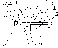
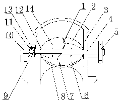
[0014] Such as figure 1 As shown, in the split sonic throttle, the throttle blade 6 is two pieces, and the driving shaft 4 is sleeved with a driven shaft 12, wherein one throttle blade 6 is fixedly connected with the driving shaft 4, and the other throttle blade 14 It is fixedly connected with the driven shaft 12 socketed on the driving shaft 4. There are sound hole bearing devices 2 and 8 respectively on the top of the two throttle blades. The sound hole bearing devices 2 and 8 are provided with sound holes 1 and 7. The driving shaft 12 is fixedly connected with the driving bevel gear 10, the driven shaft 12 is fixedly connected with the driven bevel gear 9, the driving bevel gear 10 meshes with the reverse bevel gear 11, and the reverse bevel gear 11 meshes with the driven bevel gear 9. The driven bevel gear 9 is fixed on the outside of the valve body by a pin 13 . The two throttle blades rotate 90 degrees apart.

Embodiment 2

[0016] The split sonic throttle valve of the present invention is composed of a carburetor base, a driving shaft, and a throttle blade. The driving shaft is connected to the carburetor base, and the throttle blade is fixedly connected to the driving shaft. The hole carrying device is provided with a sounding hole on the sounding hole carrying device. The throttle blade is one piece, and the bearing device of the sound hole is one of bosses or reeds.

Embodiment 3

[0018] In the split sonic throttle valve of the present invention, the throttle blade is one piece, and the throttle blade is fixedly connected with the drive shaft. There is a reed on the front of the throttle blade on one side of the drive shaft, and the opposite side of the throttle blade on the other side of the drive shaft. Bosses are arranged, and pronunciation holes are arranged on the bosses.


PUM


Abstract

The invention relates to a throttle valve of an automobile engine, in particular to a sound wave throttle valve. The side-by-side sound wave throttle valve of the invention consists of a carburetor base, a driving shaft and a throttle valve blade, wherein the driving shaft is connected with the carburetor base; the throttle valve blade is fixedly connected with the driving shaft; a sounding hole bearing device is arranged on the upside of the throttle valve blade; and a sounding hole is formed on the sounding hole bearing device. When the side-by-side sound wave throttle valve of the invention is used, the transmission speed of a flame in a combustion process is improved; explosive thrust is increased, the fuel consumption is reduced; the exhaust emission is greatly reduced; the engine power is enhanced; and thus, the aims of self-cleaning in the engine, saving oil and reducing emission are achieved.

Description

technical field [0001] The invention relates to an automobile engine throttle, in particular to a sonic throttle. Background technique [0002] CN85106920 "Gasoline engine carburetor swirl throttle", is made up of carburetor base, throttle blade and throttle shaft, and its main body is carburetor base, and throttle shaft A and throttle shaft B are separated from carburetor base two respectively. Insert the shaft hole at one end of shaft A and make the shaft pin at one end of shaft A and the shaft hole at one end of shaft B fit in a clearance fit, so that they support each other. The intake air of the throttle valve of this kind of automobile engine is insufficient, the pump air loss is large, and the air intake of each cylinder is uneven, resulting in incomplete combustion, poor emission, no energy saving, and short service life of the engine. Contents of the invention [0003] The object of the invention is to overcome the defects of the prior art, and to provide a car e...

Claims


Application Information

Patent Timeline
Patent Type & Authority Applications(China)
IPC IPC(8): F02D9/10
Inventor 张莉萍
Owner 张莉萍
Why Eureka
Try Eureka