
Isolated high-voltage leakage current measuring method and device

A leakage current, measuring device technology, applied in the direction of measuring devices, measuring electricity, measuring electrical variables, etc., can solve the problems of inability to see clearly, low accuracy, low brightness, etc., to achieve stable and reliable data transmission, low power consumption, satisfying Effect of insulation requirements

Inactive Publication Date: 2010-09-08
SHANGHAI MUNICIPAL ELECTRIC POWER CO
View PDF0 Cites 11 Cited by
  • Summary
  • Abstract
  • Description
  • Claims
  • Application Information

AI Technical Summary

Problems solved by technology

[0006] (1) The viewing angle of the display screen is not very large, and the operator needs to face up to the display screen of the microammeter to see clearly;
[0007] (2) When there is sunlight, it is basically impossible to see clearly, and the related operations are mostly carried out outdoors. In sunny weather, the readings cannot be seen clearly with the existing leakage current meter under sunlight;
[0008] (3) The display numbers are small, the brightness is low, and it is not easy to see clearly when the distance is greater than 2 meters. When doing the lightning arrester test, the maximum output voltage of the DC high voltage generator is above 150kV, and the safe distance should be at least 2 meters.
Due to the small leakage current, which belongs to the microampere level current, and the complex distribution parameters of the high-voltage generator, the accuracy of this indirect measurement method is very low, which affects the accurate judgment of the measurement status

Method used


Image

  • Isolated high-voltage leakage current measuring method and device
  • Isolated high-voltage leakage current measuring method and device
  • Isolated high-voltage leakage current measuring method and device

Examples


Embodiment Construction

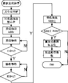
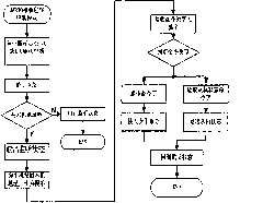
[0043] The present invention can be described in further detail by the following examples, see Figure 1 to Figure 14 shown.

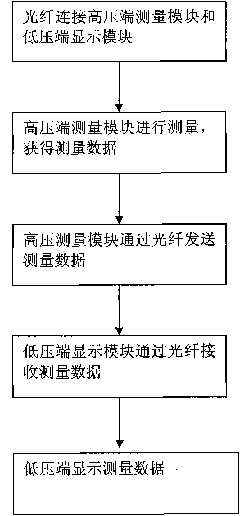
[0044] Such as figure 1 As shown, the present invention provides an isolated high-voltage leakage current measurement method, which is applied to a high-voltage leakage current measurement device, and the measurement method includes at least the following steps:

[0045] (1) The high-voltage leakage current measurement device is divided into two parts: a high-voltage end measurement module and a low-voltage end display module. An optical fiber is connected to the high-voltage end measurement module to the low-voltage end display module, thereby isolating the high-voltage end measurement module and the low-voltage end display module;

[0046] (2) The high-voltage terminal measurement module performs measurement and obtains measurement data;

[0047] (3) The measurement module at the high-voltage end sends measurement data to the display module at the ...


PUM


Abstract

The invention provides an isolated high-voltage leakage current measuring method. A high-voltage end current measuring module and a low-voltage end current display module of a high-voltage leakage current measuring device are connected with each other through an optical fiber. Measuring data of the high-voltage end measuring module is transmitted to the low-voltage end display module by the optical fiber so as to isolate the high-voltage end measuring module from the low-voltage end display module. The measuring data is transmitted by the optical fiber, so that the operator can keep away from the high-voltage output end to clearly read the measuring data. The invention also provides an isolated high-voltage leakage current measuring device.

Description

technical field [0001] The invention relates to the technical field of measurement and control of electric power system electronic instruments, in particular to an isolated high-voltage leakage current measurement method and device. Background technique [0002] In the power system, it is often necessary to measure the output current at the high-voltage output end of the high-voltage generator. For example, in the transfer and preventive tests of zinc oxide arresters, it is necessary to measure the output current at the high-voltage side of the DC high-voltage generator. In addition, in the leakage current test of oil circuit breaker and transformer winding, it is also necessary to measure the output current of the high voltage end. [0003] There are currently two ways to measure the output current: [0004] 1. Using a microammeter to measure [0005] Because the microammeter is in the high-voltage field when it works, it cannot be powered from the low-voltage side. Now i...

Claims


Application Information

Patent Timeline
Patent Type & Authority Applications(China)
IPC IPC(8): G01R31/02
Inventor 周录波黄敏吴剑敏
Owner SHANGHAI MUNICIPAL ELECTRIC POWER CO
Learn More