
Assembling system

An assembly system and assembly area technology, applied in installation, optics, instruments, etc., can solve problems such as difficult to accurately control the movement of assembly nozzles, misalignment of optical axes, and decline in assembly yield, so as to reduce assembly costs and improve assembly The effect of yield rate and simple structure

Inactive Publication Date: 2012-12-19
HONG FU JIN PRECISION IND (SHENZHEN) CO LTD +1
View PDF0 Cites 0 Cited by
  • Summary
  • Abstract
  • Description
  • Claims
  • Application Information

AI Technical Summary

Problems solved by technology

However, in the actual assembly production process, it is difficult to accurately control the movement stroke of each assembly suction nozzle, thus it is easy to cause the optical axis misalignment of each optical element in the lens module due to the error of the movement stroke of the assembly suction nozzle, and further Causes a drop in assembly yield

Method used


Image

  • Assembling system
  • Assembling system
  • Assembling system

Examples


Embodiment Construction

[0017] The assembly system provided by the technical solution will be further described in detail below in conjunction with the drawings and multiple embodiments.

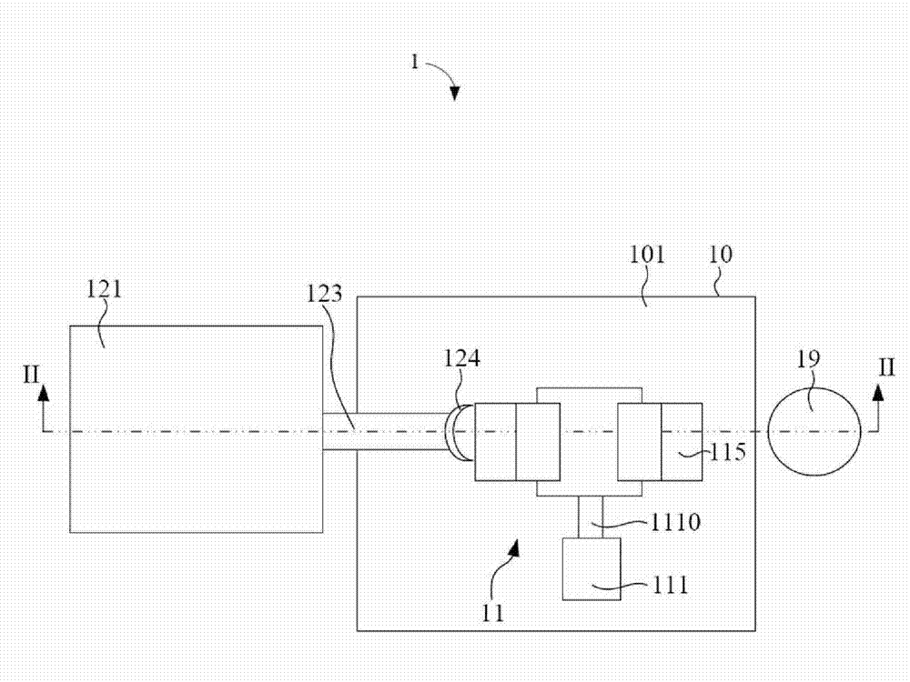
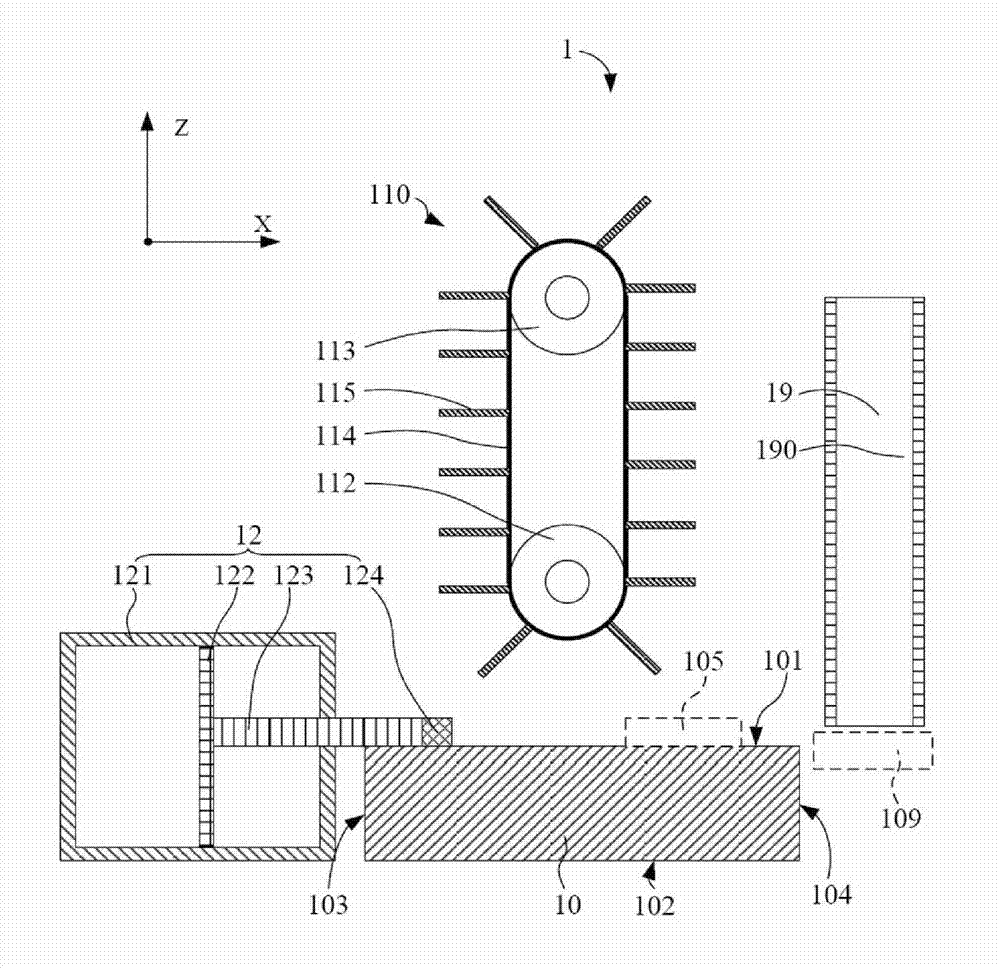
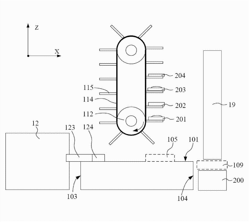
[0018] Please also refer to Figure 1 to Figure 2 The assembly system 1 provided by the first embodiment of the technical solution is used to assemble multiple optical elements into the lens barrel, which includes a carrier table 10 , a first conveying device 11 , a first pushing device 12 and an assembly suction nozzle 19 .

[0019] The carrying platform 10 is rectangular parallelepiped and has a carrying surface 101 , a bottom surface 102 , a first side 103 and a second side 104 . The carrying surface 101 is opposite to the bottom surface 102 and is used for carrying optical components. The first side 103 and the second side 104 are opposite, and both are connected between the bearing surface 101 and the bottom surface 102 .

[0020] The first conveying device 11 is disposed above the carrying platform 10 and o...


PUM


Abstract

The invention provides an assembling system, which is used for assembling optical elements into a lens cone. The assembling system comprises a first conveying device, a first material pushing device and an assembling suction nozzle, wherein the first conveying device is used for conveying the optical elements to a first material waiting region, the first material pushing device is arranged at oneside of the first conveying device, corresponds to the first material waiting region, and is used for pushing the optical elements from the first material waiting region to the assembling region in the first axial direction, and the assembling suction nozzle is arranged at the other side of the first conveying device, corresponds to the assembling region and the lens cone, and is used for suckingthe optical elements and assembling the optical elements into the lens cone from the assembling region in the second axial direction in orthogonality with the first axial direction. The assembling system with the technical scheme can reduce the moving stroke of the assembling suction nozzle.

Description

technical field [0001] The invention relates to assembly technology, in particular to an assembly system for assembling lenses into lens barrels. Background technique [0002] With the development of camera technology, lens modules are widely used in camera devices for various purposes, and the combination of lens modules with various portable electronic devices, such as mobile phones, is favored by many consumers. [0003] A lens module generally includes a lens barrel and one or more optical elements assembled in the lens barrel, and the optical elements may be lenses, infrared cut filters, spacer rings, and the like. When assembling the lens module, multiple optical components are usually carried by the tray, and the lens barrel is usually fixed on a base. Use multiple assembly suction nozzles to move down and suck the multiple optical components in the tray respectively, and translate them to the top of the lens barrel , and move down sequentially to assemble a pluralit...

Claims


Application Information

Patent Timeline
Patent Type & Authority Patents(China)
IPC IPC(8): G02B7/02
Inventor 林奕村
Owner HONG FU JIN PRECISION IND (SHENZHEN) CO LTD
Learn More