Reflection-type optical engine

An optical engine and reflective technology, which is applied in optics, optical components, lighting devices, etc., can solve the problems of increasing the volume of the optical engine, and achieve the effects of easy operation, improved light efficiency, and reduced volume

Inactive Publication Date: 2010-09-08
SHANGHAI SANXIN TECH DEV
View PDF0 Cites 8 Cited by
  • Summary
  • Abstract
  • Description
  • Claims
  • Application Information

AI Technical Summary

Problems solved by technology

However, in order to achieve the above effects, three optical elements (beam shaper and two objective lenses) need to be arranged according to a certain distance, which results in an increase in the volume of the optical engine

Method used


Image

  • Reflection-type optical engine
  • Reflection-type optical engine
  • Reflection-type optical engine

Examples


Embodiment Construction

[0024] In the following description, many technical details are proposed in order to enable readers to better understand the application. However, those skilled in the art can understand that without these technical details and various changes and modifications based on the following implementation modes, the technical solution claimed in each claim of the present application can be realized.

[0025] In order to make the purpose, technical solution and advantages of the present invention clearer, the following will further describe the implementation of the present invention in detail in conjunction with the accompanying drawings.

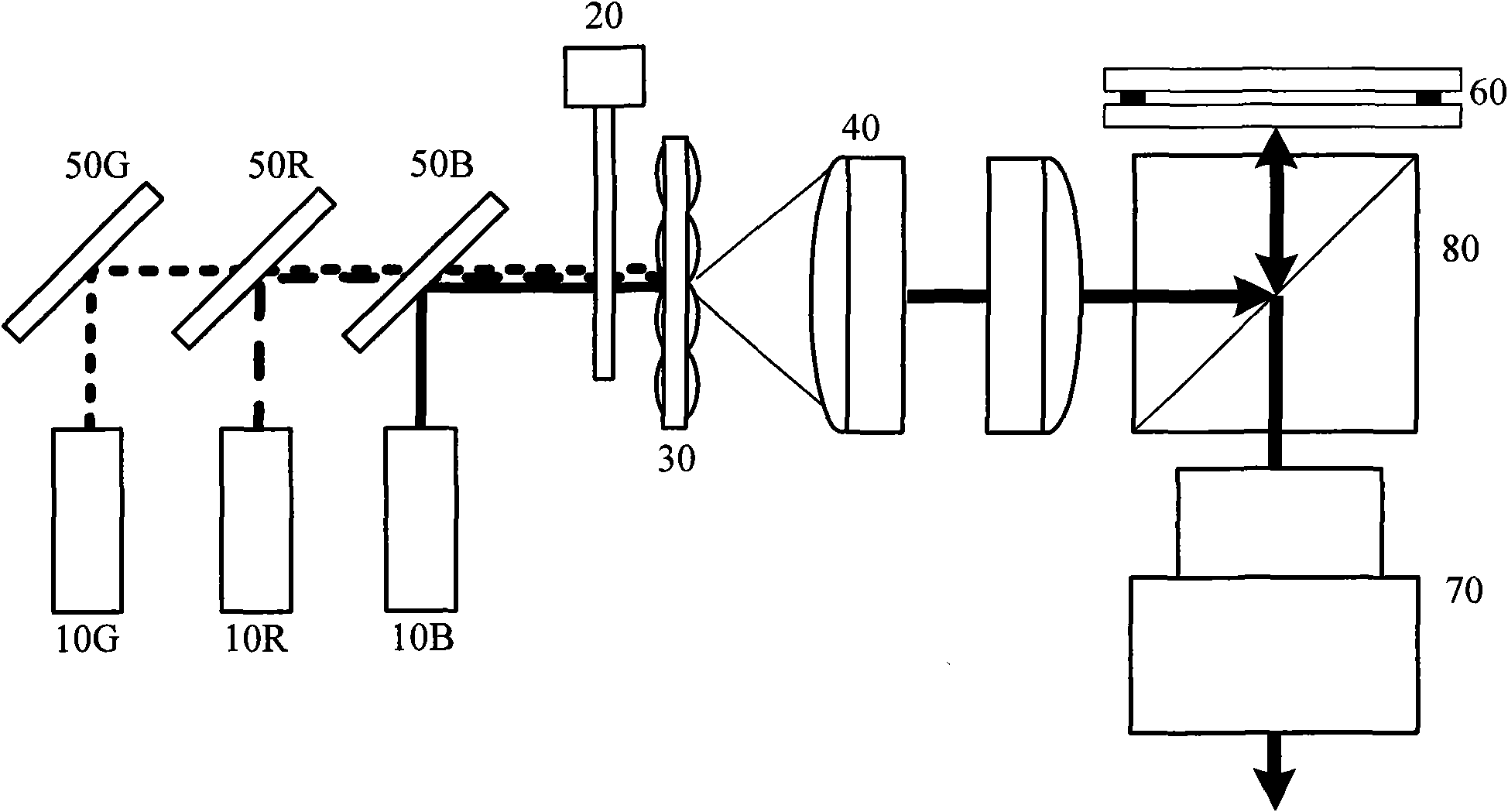
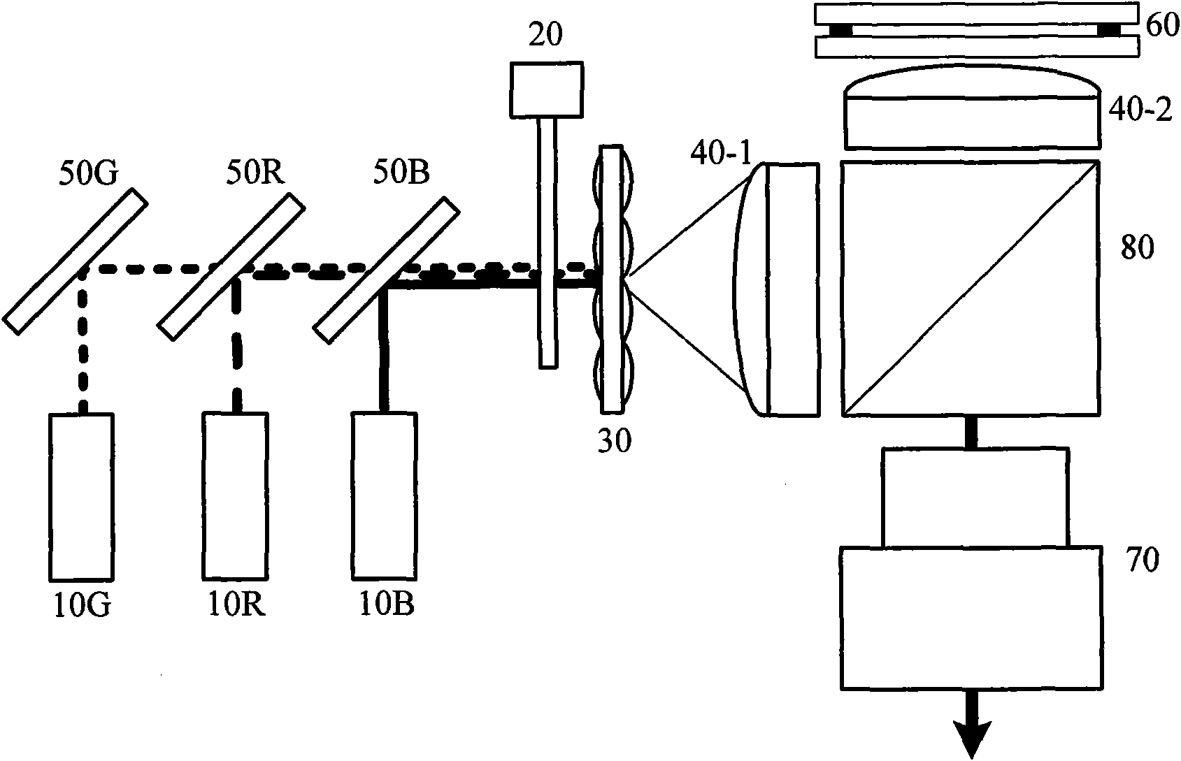
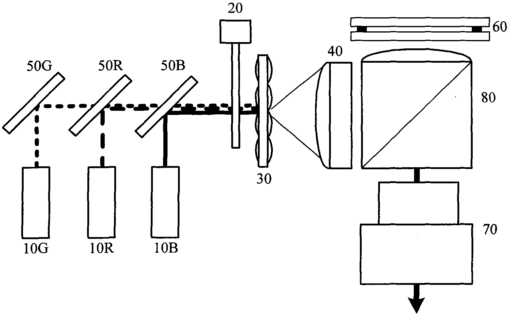
[0026] The first embodiment of the present invention relates to a reflective optical engine, the structure of which is as follows figure 2 shown.

[0027] This reflective optical engine comprises: R light source (10R), G light source (10G), B light source (10B), dichroic mirror 50R, 40G, 50B, diffuser (20), beam shaper (30), objective lens ( 40...


PUM


Abstract

The invention refers to a portable micro-projector, and discloses a reflection-type optical engine. In the invention, a polarizing beam splitter is placed with a spacing distance necessarily kept between two objective lenses for sharing space, thereby maintaining the spacing distance required between the two objective lenses and saving the space so as to reduce the volume of the optical engine. Furthermore, one or more lenses of the objective lenses can be integrally formed with the polarizing beam splitter so as to improve the precision of the optical engine assembly. Through integral formation of the optical element between the polarizing beam splitter and the optical modulator with the polarizing beam splitter, the liquid crystal optical valve can be arranged closer to the polarizing beam splitter.

Description

technical field [0001] The invention relates to a portable miniature projector, in particular to the miniaturization technology of the portable miniature projector. Background technique [0002] In order to put into practical use portable pico projectors that are smaller than the palm of your hand or projectors that are designed to be embedded in devices such as notebooks, it is necessary to develop an optical engine for projectors that is small in size. [0003] The structure of the traditional reflective optical engine is as follows figure 1 As shown, 10R is a red light source, 10G is a green light source, 10B is a blue light source, 20 is a diffuser, 30 is a beam shaper, 40 is an objective lens, 50R, 50G and 50B are dichroic mirrors for red, green and blue , 60 is a light modulator, 70 is a projection lens, 80 is a polarizing beam splitter (Polarizing Beam Splitter, referred to as "PBS"). In order to reduce the volume of the reflective optical engine, it is necessary to...

Claims


Application Information

Patent Timeline
Patent Type & Authority Applications(China)
IPC IPC(8): G03B21/14G03B21/20G02B27/09F21V13/00
CPCG03B21/14G03B21/2073
Inventor 林伦辰李东珍金城守
Owner SHANGHAI SANXIN TECH DEV
Why Eureka
Try Eureka