Exhaust-gas secondary treatment preceding a turbocharger

A technology for exhaust aftertreatment and turbocharger, which is used in exhaust devices, machines/engines, air quality improvement, etc.

Active Publication Date: 2010-09-08
EMITEC EMISSIONSTECHNIK +1
View PDF0 Cites 2 Cited by
  • Summary
  • Abstract
  • Description
  • Claims
  • Application Information

AI Technical Summary

Problems solved by technology

[0003] Particularly in the context of the above, an exhaust gas treatment system should be proposed which at least partly solves the above technical difficulties and problems

Method used


Image

  • Exhaust-gas secondary treatment preceding a turbocharger
  • Exhaust-gas secondary treatment preceding a turbocharger
  • Exhaust-gas secondary treatment preceding a turbocharger

Examples


Embodiment Construction

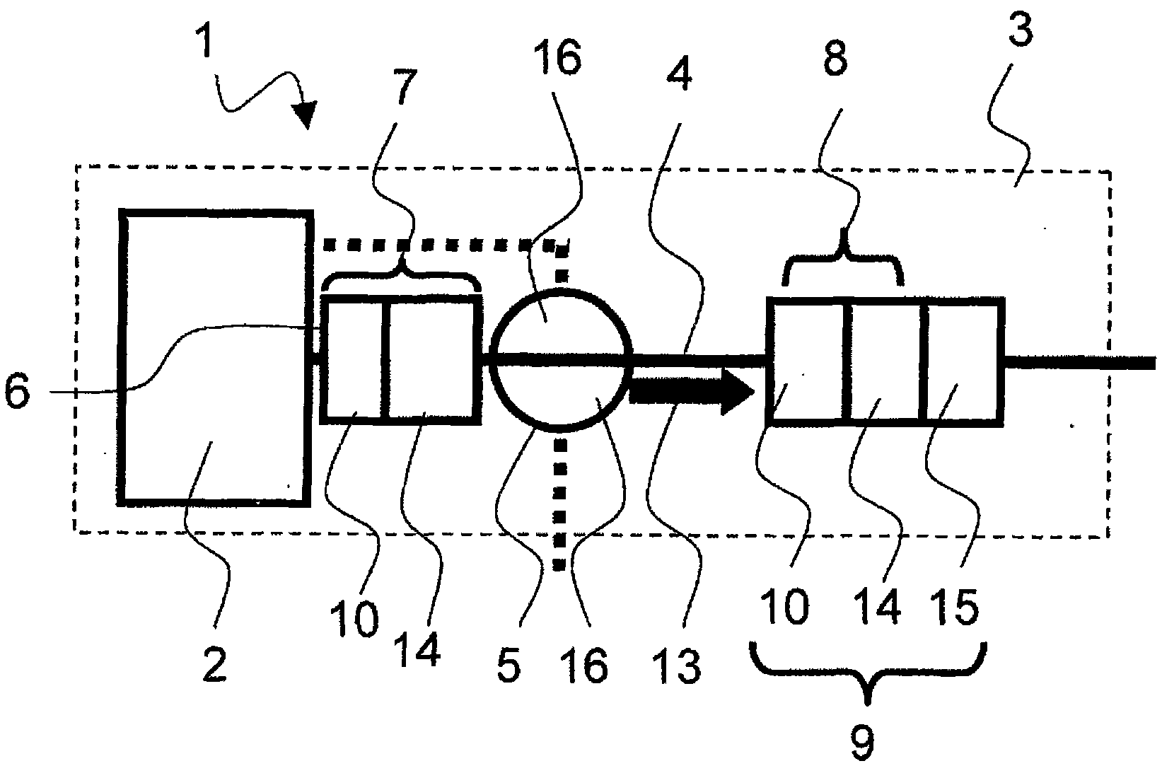
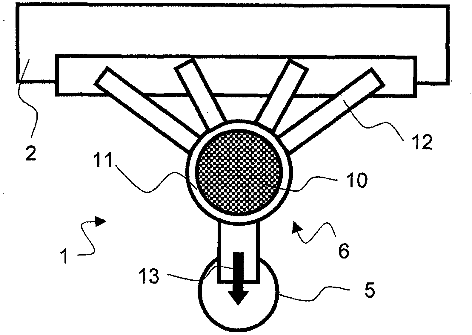
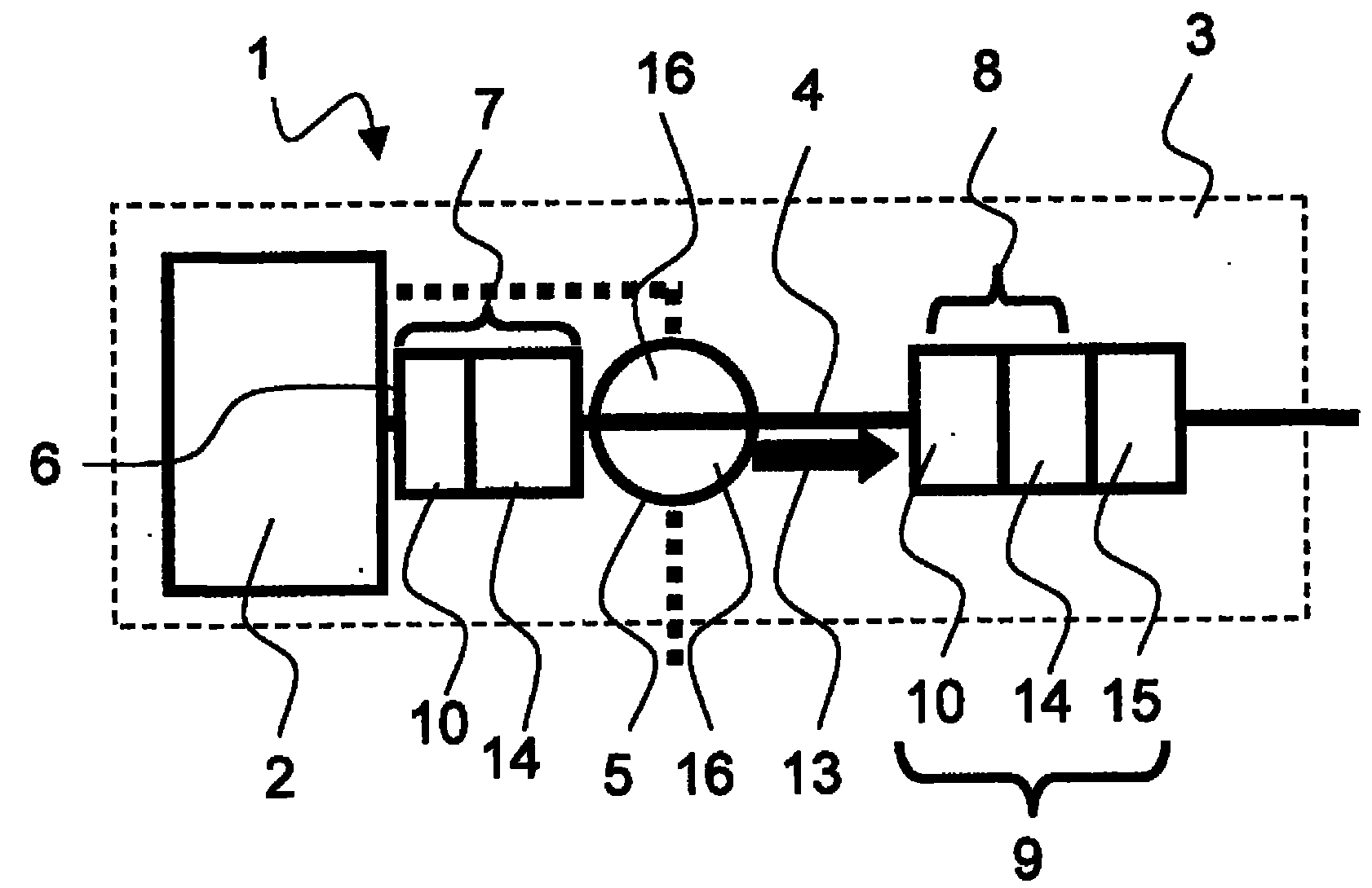
[0022] exist figure 1A vehicle 3 with a diesel internal combustion engine 2 is schematically shown, wherein the exhaust gas generated in the internal combustion engine passes through an exhaust gas aftertreatment system 1 . In the example shown here, the exhaust gas flows in the flow direction 13 first through the exhaust gas converter 6 , then through the turbocharger 5 (formed by two (charging) stages 16 ), after which the exhaust gas continues through the The exhaust pipe 4 leads, for example, into the underbody of the vehicle 3 in which further exhaust gas aftertreatment units 9 are arranged, for example an oxidation catalytic converter 10 , a particle separator 14 , an SCR catalytic converter 15 .

[0023] In this case, the exhaust gas converter 6 arranged between the internal combustion engine 2 and the turbocharger 5 has a first volume 7 which is larger than a second volume 8 of an exhaust gas aftertreatment unit 9 having the same function. Here, the exhaust gas conver...


PUM


Abstract

The invention relates to an exhaust-gas secondary treatment system (1) for an internal combustion engine (2) of a vehicle (3) having at least one exhaust pipe (4) and at least one turbocharger (5) and at least one exhaust converter (6), wherein the catalytic converter (6) is provided between the internal combustion engine (3) and the minimum of one turbocharger (5) that has an initial volume (7) of at least 0.6 liters.

Description

technical field [0001] The invention relates to an exhaust gas aftertreatment system for a vehicle internal combustion engine, which has at least one exhaust gas tract, at least one turbocharger and at least one exhaust gas converter. The exhaust gas aftertreatment system relates in particular to a system for exhaust gas aftertreatment of a lean-burn engine of a passenger vehicle. Background technique [0002] In the past, the general emphasis was on compliance with gasoline engine exhaust regulations, however recently this has changed. The importance of the environmental impact caused by diesel engines has increased among the public. The reasons for this are: firstly, the specific health hazards posed by particulate emissions from such engines are considered; and secondly, the number of diesel vehicles registered in Europe has risen dramatically. The reason for this rise is not only economic, but also due to the (very good) driving behavior of vehicles with modern diesel ...

Claims


Application Information

Patent Timeline
Patent Type & Authority Applications(China)
IPC IPC(8): F01N3/023F01N3/035F01N37/00
CPCF01N3/2006F02B37/02F01N3/035F01N2340/00F01N13/02Y02T10/26F01N3/023F02B37/00Y02T10/144F01N2340/06F01N13/009Y02A50/20Y02T10/12
Inventor R·布吕科V·乔尔格
Owner EMITEC EMISSIONSTECHNIK
Why Eureka
Try Eureka