Visualized medical auxiliary inspection equipment

A technology for auxiliary inspection and equipment, applied in the field of medical devices, can solve the problems of no objective file, high cost, single function, etc., and achieve the effect of simple and compact internal structure, lower production cost, and single optical element

Inactive Publication Date: 2010-09-15
孙渝超 +1
View PDF0 Cites 1 Cited by
  • Summary
  • Abstract
  • Description
  • Claims
  • Application Information

AI Technical Summary

Problems solved by technology

[0002] Due to the failure of basic inspection equipment such as frontal mirror, indirect laryngoscope, ophthalmoscope, and retinoscopy to save the images seen, it is common for departments such as otolaryngology, ophthalmology, and stomatology that most diagnostic evidence cannot be saved. In case analysis, telemedicine, etc. , scientific research, and medical dispute handling without objective archives reference
At the same time, most of these devices can only be watched independently by observers, and there are many inconveniences in the teaching process. Teachers cannot demonstrate to multiple people at the same time when teaching a certain inspection method
Although existing equipment such as electronic laryngoscopes and fundus cameras can capture image data, they are bulky, single-function, and expensive, and are not suitable for general inspection and medical teaching.

Method used


Image

  • Visualized medical auxiliary inspection equipment
  • Visualized medical auxiliary inspection equipment
  • Visualized medical auxiliary inspection equipment

Examples


Embodiment Construction

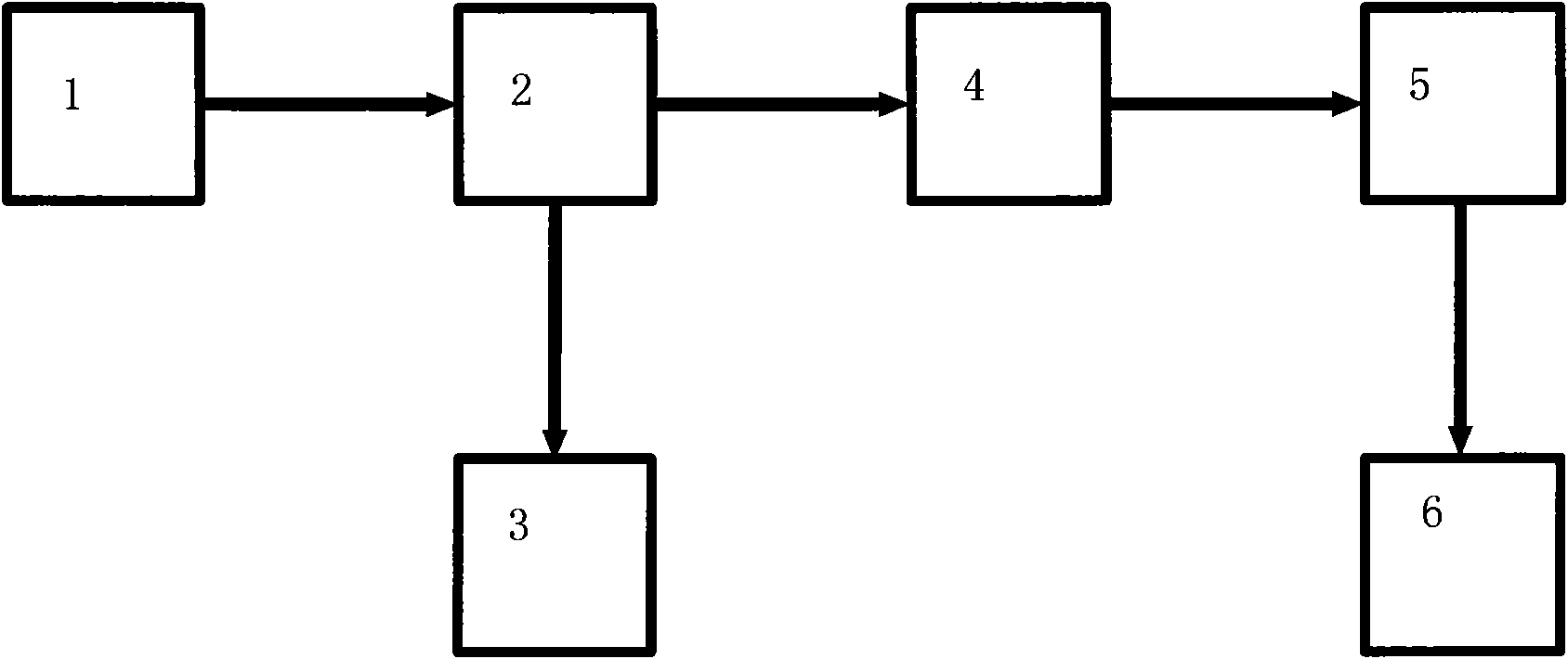
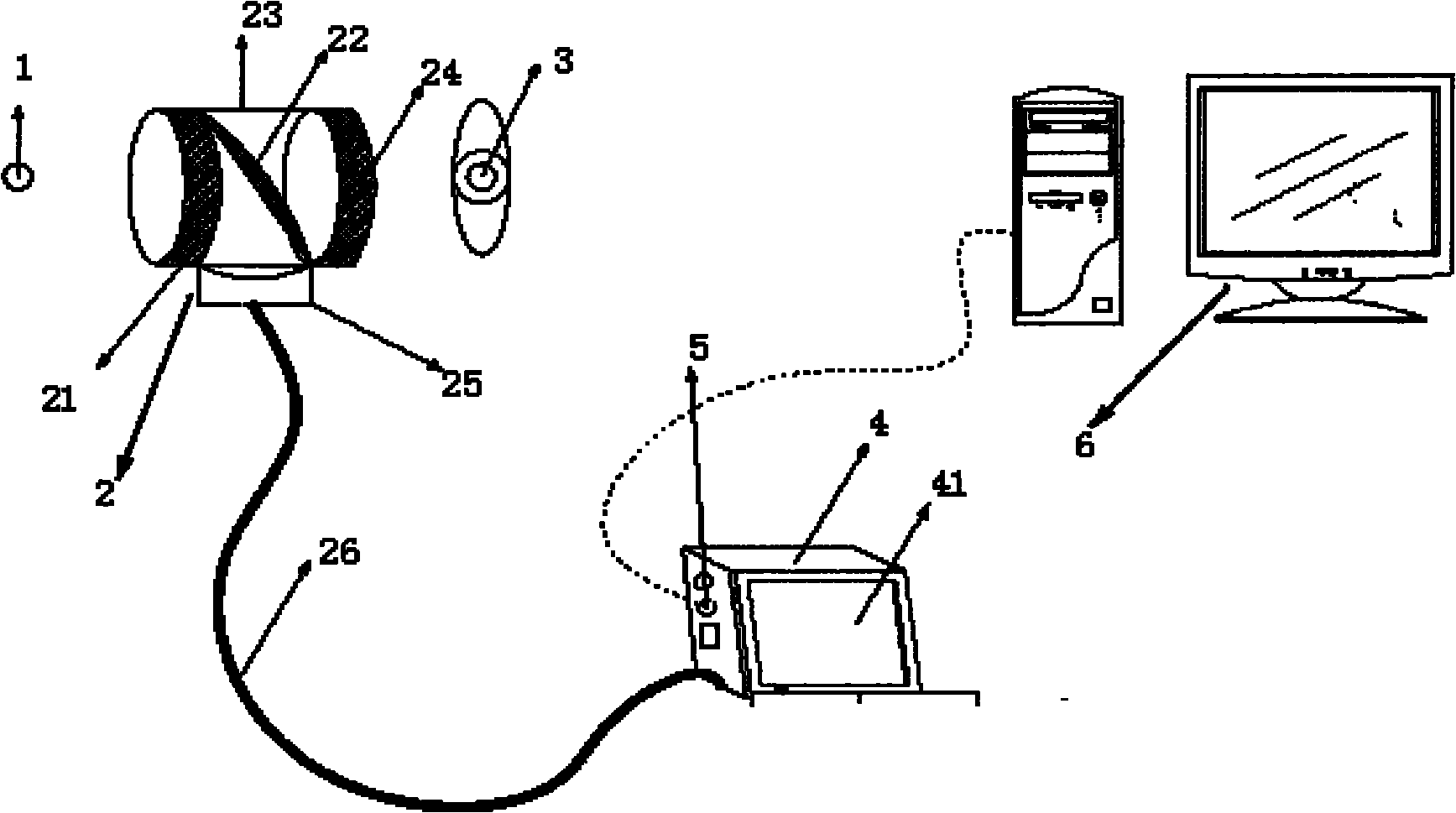
[0012] see figure 1 , figure 2 and image 3 , the present invention comprises observation system 2 and imaging device 4, and the housing of observation system 2 is a cylindrical shape, and beam splitter 22 is arranged in the housing, and the two ends of housing are respectively provided with eyepiece 24 and objective lens 21, and mechanical support 23 is provided with On the periphery of the housing, the optical fiber connector 25 is arranged on the lower side of the housing and is connected with the optical fiber 26; the imaging device 4 is provided with an LCD display 41, and the imaging device 4 is connected with the other end of the optical fiber 26, and the output of the imaging device 4 , the communication interface 5 is connected with several displays or computer equipment 6 . The mechanical support 23 is fixed on the frenulum. The observed scene 1 is divided into two beams by the beam splitter 22 through the observation system 2, one beam is injected into the obser...


PUM


Abstract

The invention relates to visualized medical auxiliary inspection equipment, belonging to the technical field of medical appliances. The visualized medical auxiliary inspection equipment not only can process clinical inspection data but also can demonstrate to many people in time, thereby being convenient for teaching activities. The visualized medical auxiliary inspection equipment of the invention comprises an observing system and an imaging device, wherein the observing system has a barrel-shaped shell and is provided with an ocular lens, an objective lens, a spectroscope, an optical fiber interface and a mechanical supporting seat, and the optical fiber interface is connected with the imaging device through optical fibers. The invention has the advantages of small volume, low cost and convenient use. When in use, the scene seen by a user who wears the visualized medical auxiliary inspection equipment is shown on the imaging system or other external equipment. The visualized medical auxiliary inspection equipment can be widely applied to scientific research, teaching and medical diagnosis and identification and especially medical diagnosis and teaching of frontal mirrors, indirect laryngoscopes, ophthalmoscopes, skiascopes and other equipment which only can be independently observed by observers, can also be used for drawing, shooting and recording of teaching data, scientific research data and clinical data, and is beneficial to research analysis, teaching demonstration, consultation identification and other works.

Description

Technical field [0001] The invention belongs to the field of medical devices, in particular to a visual medical auxiliary inspection device. Background technique [0002] Due to the failure of basic inspection equipment such as frontal mirror, indirect laryngoscope, ophthalmoscope, and retinoscopy to save the images seen, it is common for departments such as otolaryngology, ophthalmology, and stomatology that most diagnostic evidence cannot be saved. In case analysis, telemedicine, etc. , scientific research, and medical dispute handling have no objective archives to refer to. At the same time, most of these devices can only be watched independently by observers, and there are many inconveniences in the teaching process. When teaching a certain inspection method, the teacher cannot demonstrate it to multiple people at the same time. Although existing equipment such as electronic laryngoscopes and fundus cameras can capture image data, the equipment is bulky, single-function...

Claims


Application Information

Patent Timeline
Patent Type & Authority Applications(China)
IPC IPC(8): A61B19/00A61B1/04A61B1/07A61B90/00
Inventor 孙渝超孙鹏
Owner 孙渝超
Why Eureka
Try Eureka