Movable baking and drying machine

A drying machine, mobile technology, applied in drying, hearth furnace, drying solid materials, etc., can solve the problems of increasing air humidity, low work efficiency, high energy consumption, etc., and achieves convenient use and simple structure , fast drying effect

Inactive Publication Date: 2010-09-15
陈平
View PDF4 Cites 10 Cited by
  • Summary
  • Abstract
  • Description
  • Claims
  • Application Information

AI Technical Summary

Problems solved by technology

At present, dehumidification products on the market include dehumidifiers, air conditioners, etc., which have the function of converting humid air into dry air, but these devices cannot quickly solve the problem of ground drying; Drying the ground, but the function is only to evaporate the water on the ground into water vapor through the hot air. In this drying method, the ground is dry, but the water vapor in the hot air still fills the space of the site, which increases the temperature of the site. The humidity of the air, as the temperature of the ground and water vapor decreases, the humid air condenses into water droplets on the ground. Due to the open heat dissipation, the energy consumption is large and the work efficiency is low; dehumidifiers and air conditioners are very important for converting moisture into dry Although the air effect is good, it consumes a lot of energy, and the cost of construction and use are relatively high.
At present, there is no dehumidification and dehumidification device on the market that can quickly dry the moisture on the ground and walls, and at the same time convert humid air into dry air, and is easy to use, low in cost, and low in energy consumption.

Method used


Image

  • Movable baking and drying machine
  • Movable baking and drying machine
  • Movable baking and drying machine

Examples


Embodiment 1

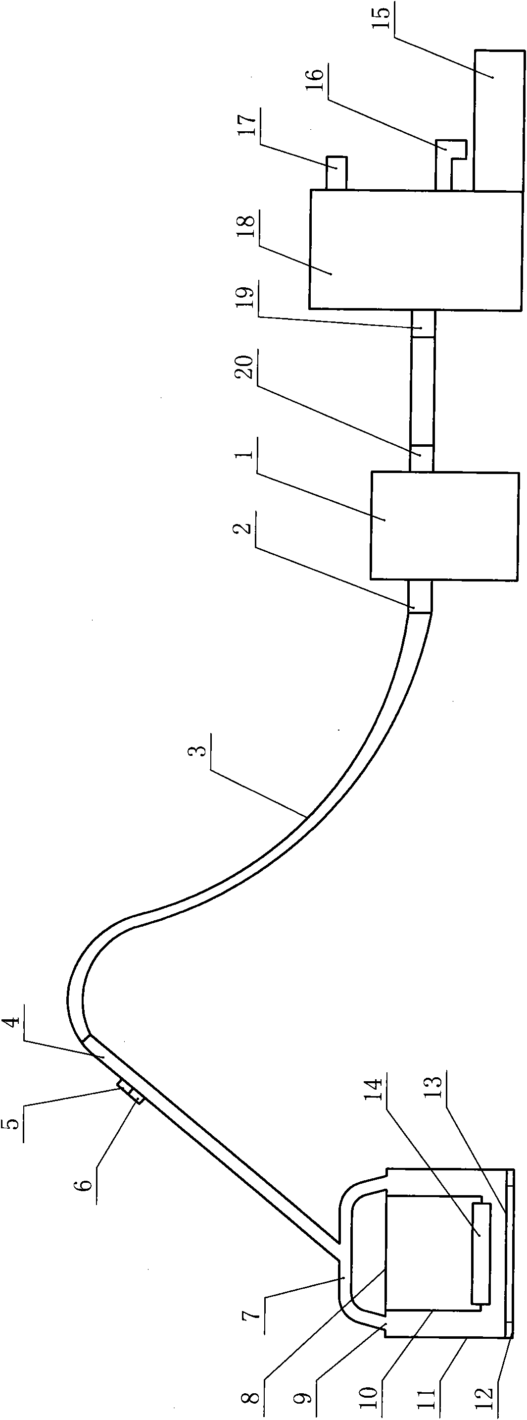
[0021] refer to figure 1 figure 2 , a mobile drying and suction dryer, which is mainly composed of an electric heating device, a gas extraction device, a water and gas separation device and a control device. The hole 9 is connected, the air outlet 20 is connected with the air inlet 19 of the water-air separation device, the water outlet 16 of the water-air separation device is equipped with a water storage tank 15, and the control device is connected with the electric heating device.

[0022] The exhaust gas device is a centrifugal exhaust fan 1 .

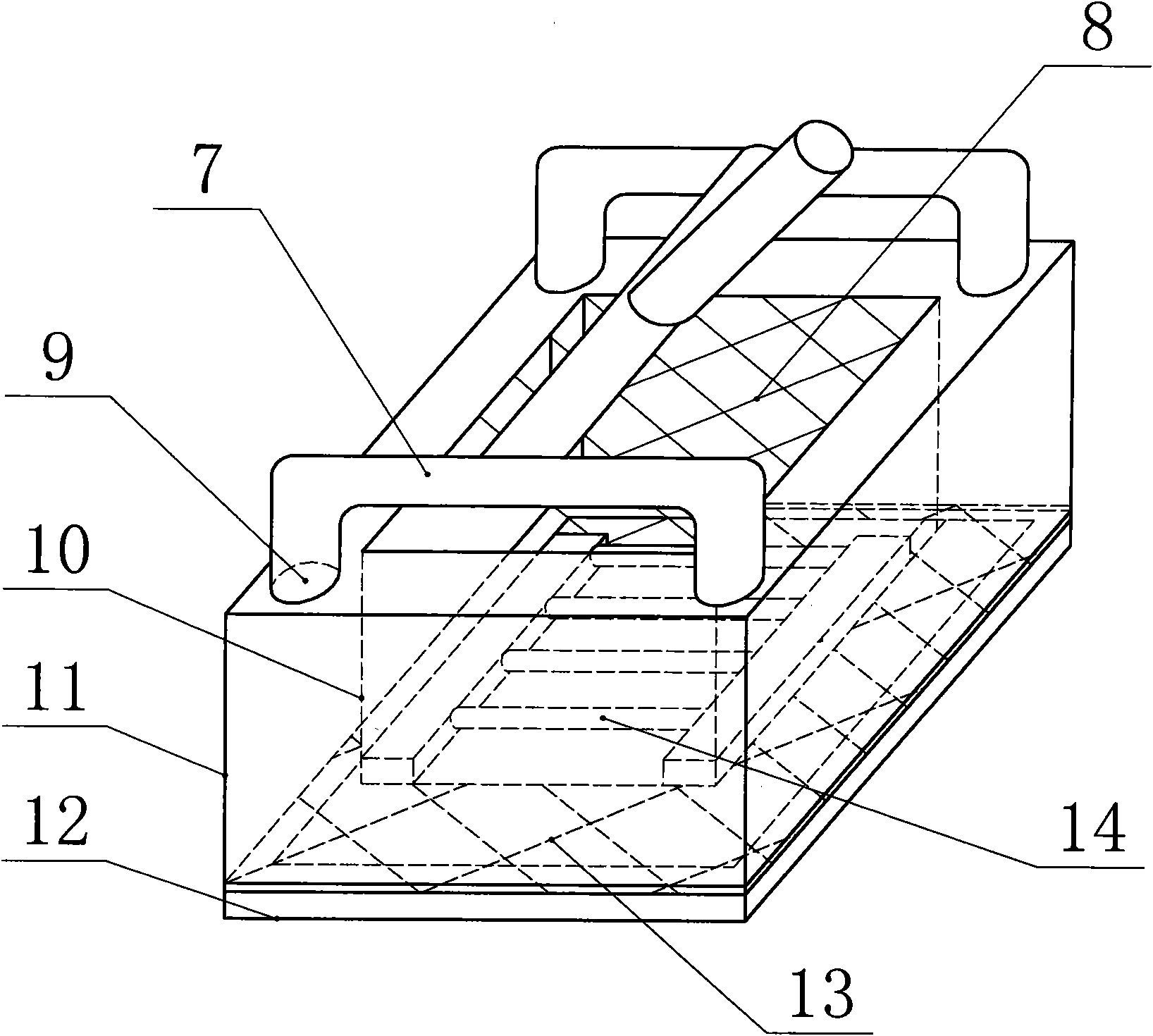
[0023] The electric heating baking device comprises an inner shell 10, an outer shell 11, an electric heating tube 14 and a sealing strip 12. The electric heating tube 14 is arranged at the bottom of the inner shell 10, and the sealing strip 12 is arranged at the lower end of the outer shell 11. Between the sides is a hollow interlayer, the upper end surface of the interlayer is closed, and the upper end surface of the interlaye...

Embodiment 2

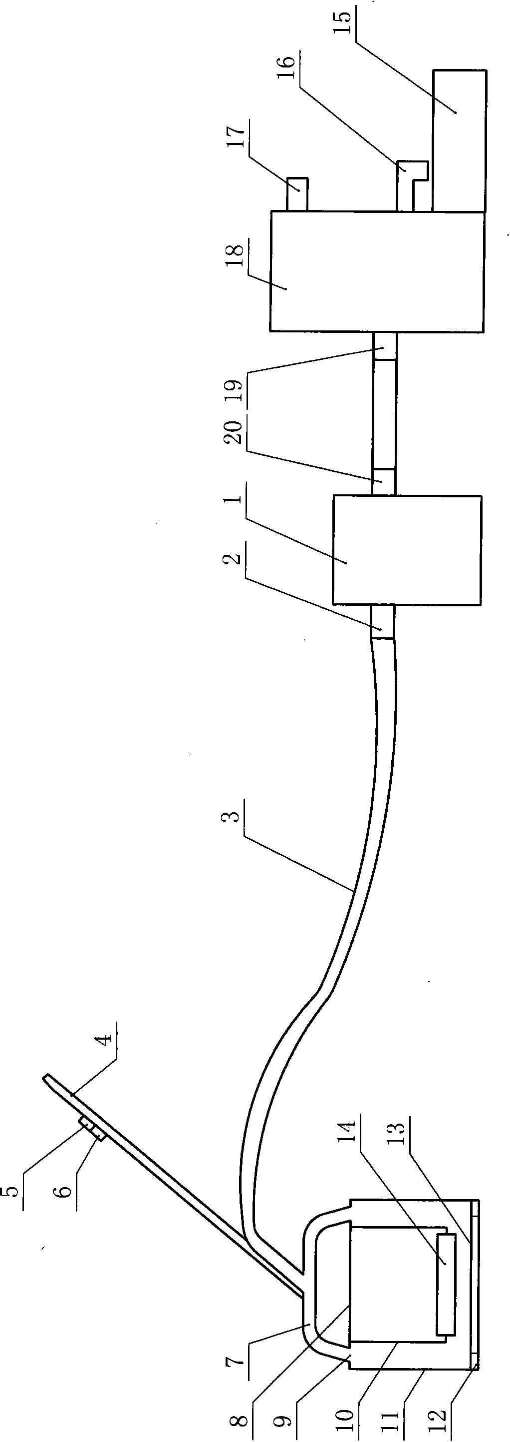
[0032] refer to image 3 , the control rod 4 in the control device adopts a rod-shaped body, and one end of the control rod 4 is connected with the electric heating device. The through hole 9 communicates with the air inlet 2 of the centrifugal exhaust fan 1 through the pipeline 3, and all the other are the same as the embodiment 1.


PUM


Abstract

The invention discloses a movable baking and drying machine, mainly comprising an electric baking device, a gas pumping and drainage device, a water and gas separation device and an operation device. The air inlet of the gas pumping and drainage device is communicated with a through hole of the electric baking device, and an air outlet is communicated with a gas inlet of the water and gas separation device; a water outlet of the water and gas separation device is provided with a water storage tank; the operation device is connected with the electric baking device; and the electric baking device comprises an outer shell, an inner shell arranged in the outer shell, an electrical heating tube arranged at the lower part of the inner shell, and a sealing bar arranged at the lower end of the outer shell. The distance between the lower end face of the inner shell and the lower end face of the outer shell is from 0.5 to 1.5 cm. A hollow interlayer is arranged between the outer side of the inner shell and the inner side of the outer shell, the upper end face of the interlayer is sealed, and the upper end ace of the interlayer is provided with a through hole which is communicated with the air inlet of the gas pumping and drainage device through a pipeline. The invention has the advantages of simple structure, low energy consumption, low cost, convenient operation, capability of drying ground and wall face rapidly and good humidity removal effect.

Description

technical field [0001] The invention relates to a drying device, in particular to a mobile drying and sucking dryer for removing indoor moisture. Background technique [0002] During the mildew rain season, due to the high humidity of the air, a lot of water condenses on the ground and walls, which affects people's normal life and work. At present, dehumidification products on the market include dehumidifiers, air conditioners, etc., which have the function of converting humid air into dry air, but these devices cannot quickly solve the problem of ground drying; Drying the ground, but the function is only to evaporate the water on the ground into water vapor through the hot air. In this drying method, the ground is dry, but the water vapor in the hot air still fills the space of the site, which increases the temperature of the site. The humidity of the air, as the temperature of the ground and water vapor decreases, the humid air condenses into water droplets on the ground....

Claims


Application Information

Patent Timeline
Patent Type & Authority Applications(China)
IPC IPC(8): B01D53/26F26B3/00
Inventor 陈平
Owner 陈平
Why Eureka
Try Eureka