Jet-driven rotary type spraying head

A spray head and rotary technology, which is applied in the field of jet propelling rotary spray heads to achieve the effects of improved spray fire extinguishing ability, good fire extinguishing effect and simplified structure

Inactive Publication Date: 2010-09-15
韩铁夫
View PDF3 Cites 29 Cited by
  • Summary
  • Abstract
  • Description
  • Claims
  • Application Information

AI Technical Summary

Problems solved by technology

[0003] The technical problem to be solved by the present invention is to provide a spray-propelled rotary spray head that uses the spray jet reaction force of th

Method used


Image

  • Jet-driven rotary type spraying head
  • Jet-driven rotary type spraying head
  • Jet-driven rotary type spraying head

Examples


Embodiment 1

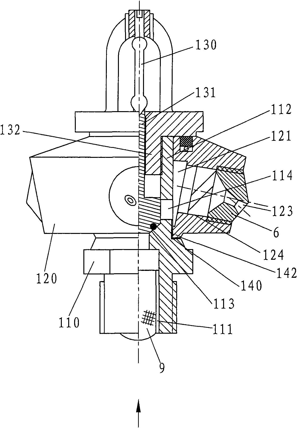
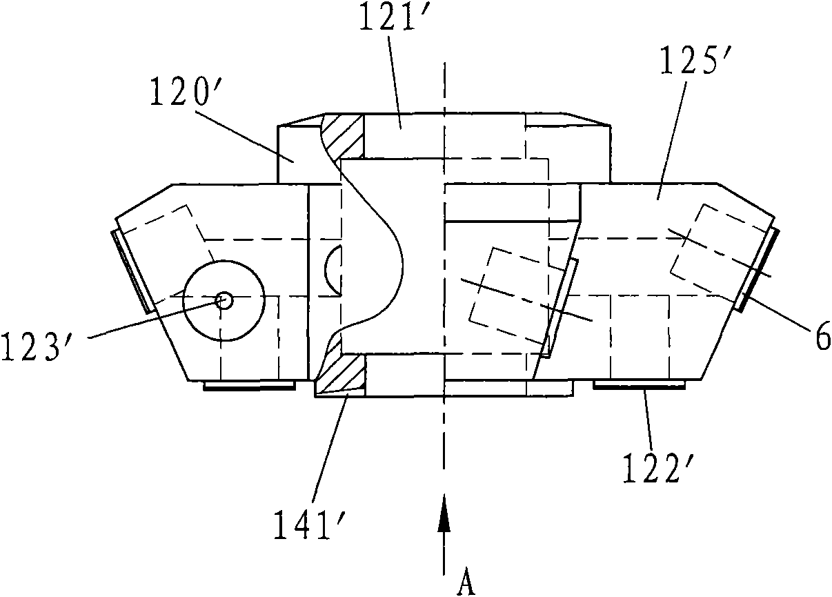
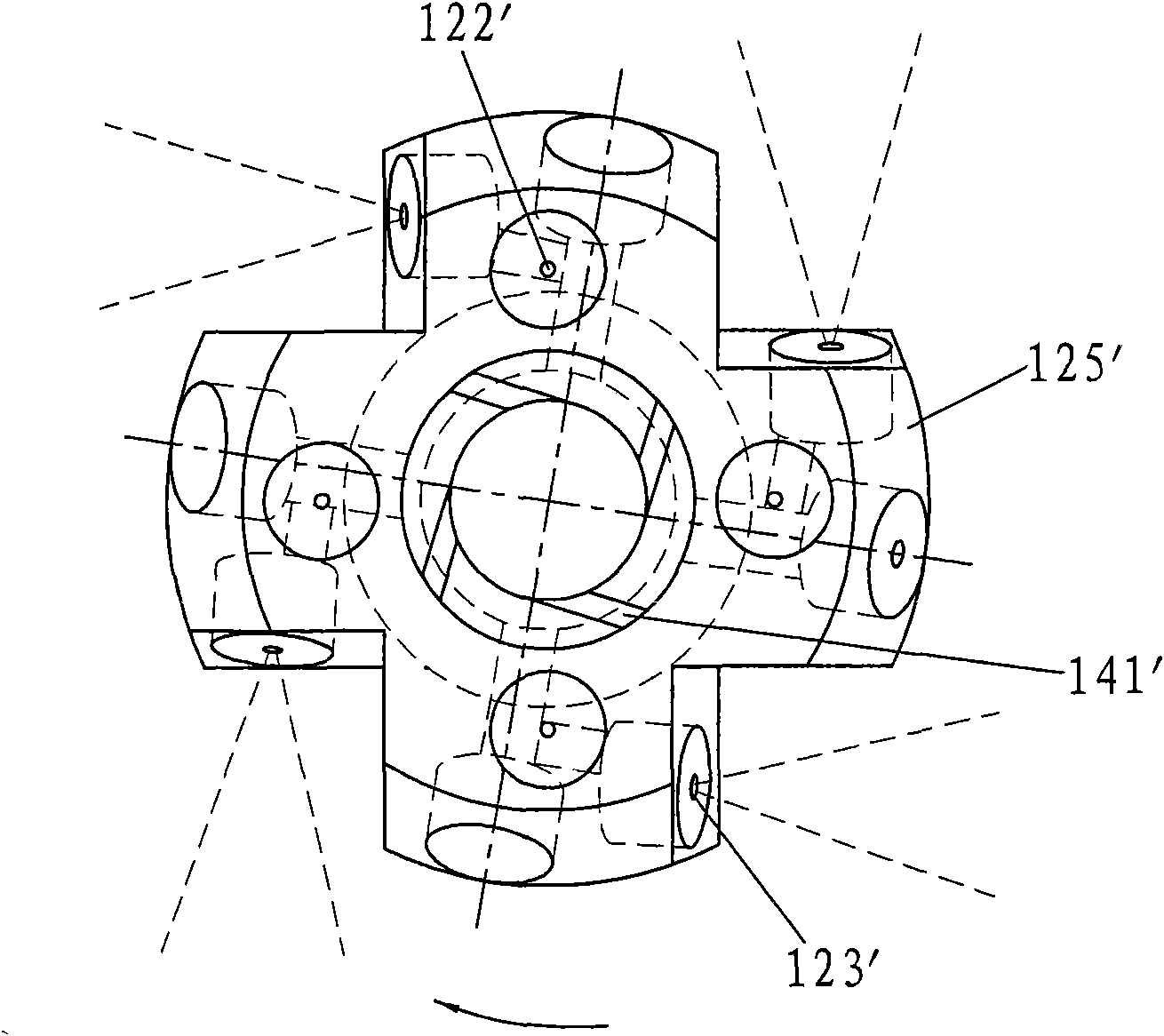
[0035] Embodiment 1: as figure 1 , Picture 1-1 and Figure 1-2 .

[0036] The jet push rotary spray head described in this embodiment is a spray push rotary closed spray head with a sleeve type spray head body, which mainly includes a seat body 110 and a spray head body 120 (such as figure 1 shown). in:

[0037] The interior of the seat body 110 is hollow, and one end thereof is an inlet 111. A filter 9 is arranged inside the inlet port 111. A screw thread is provided outside the inlet port 111 to connect with an input flow pipe (not shown in the figure). The seat body 110 is also provided with The hollow shaft 112 is provided with a through hole 114 on the wall of the hollow shaft 112 .

[0038] The nozzle body 120 is a rotary shape, and its shape can be various. In this embodiment, the nozzle body 120 is a truncated polyhedral cone with a central through hole, which is rotatably sleeved on the hollow shaft 112 of the seat body 110. The inside of the nozzle body 120 is...

Embodiment 2

[0047] Embodiment 2: as figure 2 , Figure 2-1 and Figure 2-2 shown.

[0048] The spray-push rotary spray head described in this embodiment also includes a seat body 210 and a spray head body 220 . in:

[0049] The seat body 210 is hollow inside, and its outer wall is provided with thread to connect with the input flow pipe (not shown in the figure), and the inner hole 212 and the outlet of the seat body 210 are provided with upper and lower ring surfaces 215, 216.

[0050] The nozzle body 220 is provided with an inlet pipe 226 above and a composite square body 225 below. The inlet pipe 226 is rotatably sleeved in the inner hole 212 of the seat body 210 . The outer periphery of the inlet end of the nozzle body 220 inlet pipe 226 is provided with an upper circular step 227 and a collar 224, and the outer peripheral top ring of the nozzle exposed outside the inner hole 212 of the seat body 210 forms a lower circular step 228, and the upper and lower circular steps 227, 228...

Embodiment 3

[0053] Embodiment 3: as image 3 , Figure 3-1 , Figure 3-2 and Figure 3-3 shown.

[0054] The spray-push rotary spray head described in this embodiment also includes a seat body 310 and a spray head body 320 . in:

[0055] The interior of the seat body 310 is hollow, and one end thereof is an inlet 311. The filter 9 is arranged in the inlet 311. The inlet 311 is provided with a screw thread to be connected with an input flow pipe (not shown in the figure). The inner hole of the seat body 310 Two annular surfaces 315, 316 are arranged on the top and the exit of 312.

[0056]The nozzle body 320 is in the shape of a space generatrix revolution, and its inner cavity forms a fluid channel 321. The nozzle body 320 is composed of a separate inlet pipe 326, a nozzle body seat 3201 and a nozzle body body 3202. The inlet pipe 326 can be It is rotatably nested in the inner hole 312 of the seat body 310 for radial positioning, and the inlet pipe 326 is screwed on the top of the n...


PUM


Abstract

The invention discloses a jet-driven rotary spraying head, which comprises a hollow base and a spraying head body capable of rotating relative to the base, wherein a fluid passage is arranged inside the spraying head body, and spraying orifices are formed outside the spraying head body; each spraying orifice at least comprises two eccentric spraying orifices capable of generating eccentric spraying flows; the spraying flows of the eccentric spraying orifices rotate the spraying head body; and the setting direction of each eccentric spraying orifice should make the spraying head body rotate in the same direction. A rotary matching surface is arranged between the spraying head body and the base; the spraying head body drives the spraying orifices formed thereon to rotate together, a fluid permeating the rotary matching surface is used for lubricating the rotary matching surface; at least one matching surface gap, capable of leaking the fluid outwards, in the rotary matching surface is designed into a circular seam spraying orifice; and a small amount of the fluid joins in the spraying of the spraying head through the circular seam spraying orifice. The spraying head uses spraying jet flow reacting force of the eccentric spraying orifices to cause autorotation, and can also solve the problems of large-area uniform spraying and fine atomization while working at meddle and low pressures.

Description

technical field [0001] The invention relates to a spraying device, in particular to a jet-propelled rotary spray head, which is mainly used in the field of fire-fighting and extinguishing, and can also be used as an environmental protection spray. Background technique [0002] The rotary power of some rotary sprinklers is driven by motors, but the motor drive system is complex in structure, large in size and needs to provide additional rotary power. Some rotary sprinklers driven by fluids (such as rotary sprinklers) do not have spray functions and structures suitable for fire extinguishing. The traditional water mist nozzle or fine water mist nozzle in the field of fire protection is a fixed nozzle. Due to structural limitations, it sprays unevenly, and there is a spray dead angle in the protected area. The solution is rotary spraying, which requires the use of rotary sprinklers. The Chinese utility model patent with application number 200520091525.7 discloses a large-flow ...

Claims


Application Information

Patent Timeline
IPC IPC(8): B05B3/06B05B1/18
Inventor 韩铁夫
Owner 韩铁夫
Why Eureka
Try Eureka