
Deep hole extrusion forming process of medium-carbon low-alloy structural steel

An extrusion, low-alloy technology, used in metal extrusion, metal extrusion dies, metal processing equipment, etc.

Active Publication Date: 2010-09-15
邓晓光
View PDF7 Cites 14 Cited by
  • Summary
  • Abstract
  • Description
  • Claims
  • Application Information

AI Technical Summary

Problems solved by technology

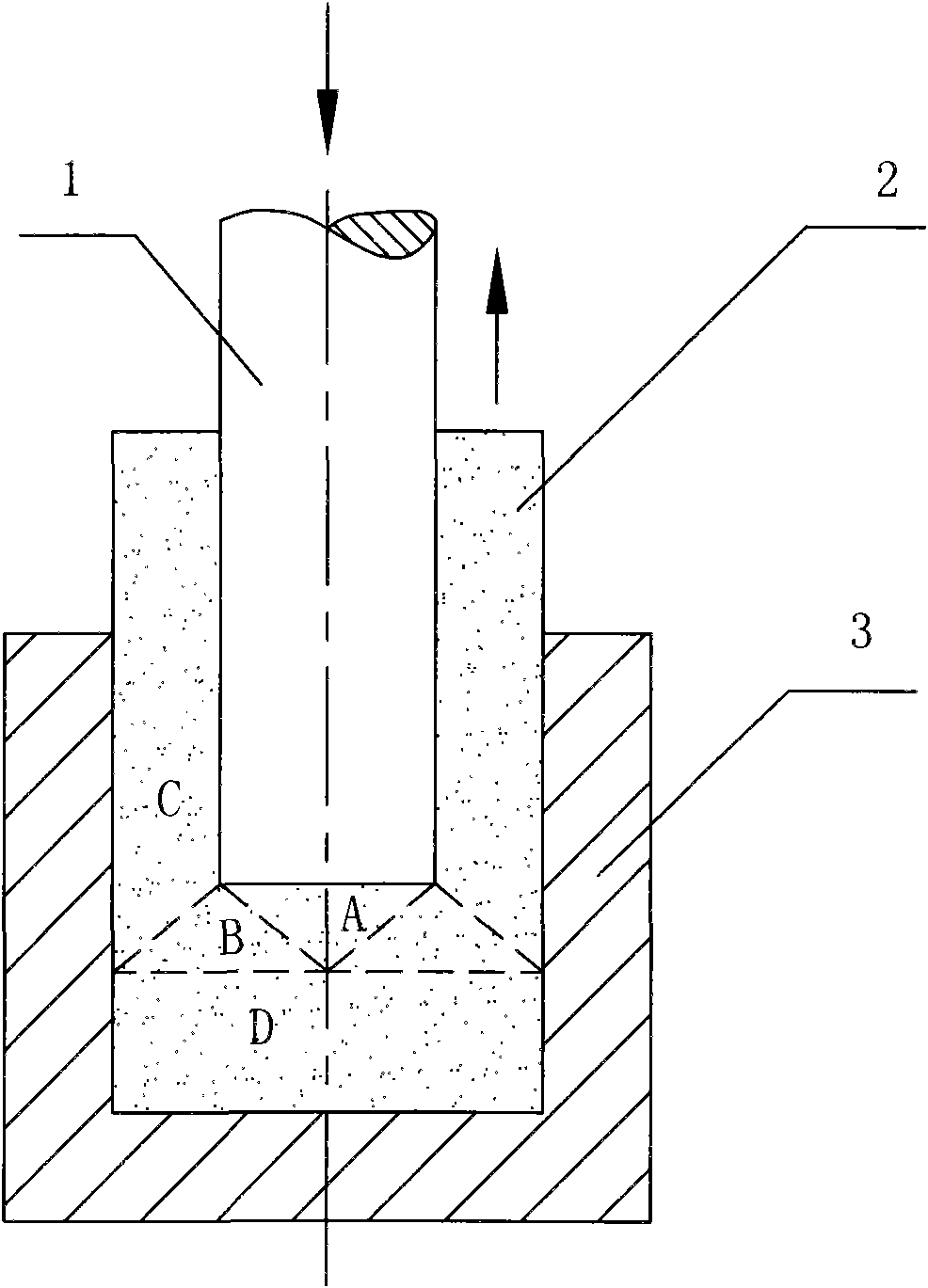
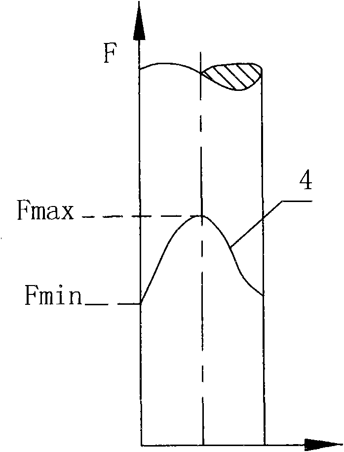
[0004] The object of the present invention is to provide a deep-hole extrusion forming process for medium-carbon low-alloy structural steel that reduces the deformation resistance of the metal during the extrusion process and reduces the eccentric force of the metal deformation resistance on the punch. Forming hollow parts with a ratio of hole depth to hole diameter greater than 5, to solve the problem of extrusion forming of slender hollow rods

Method used


Image

  • Deep hole extrusion forming process of medium-carbon low-alloy structural steel
  • Deep hole extrusion forming process of medium-carbon low-alloy structural steel
  • Deep hole extrusion forming process of medium-carbon low-alloy structural steel

Examples


Embodiment 1

[0057] The deep hole extrusion process diagram of the hollow rod made of 42CrMo:

[0058] Figure 15 Indicates the blank before extrusion, with a bar diameter of 62mm and a length of 160mm; Figure 16 Indicates the first step of deep hole extrusion, the diameter of the punch is 40 mm, the length of the working part of the punch (the length of the part in contact with the blank) is 160 mm, the diameter of the extrusion hole in the first step is 40 mm, and the depth of the extrusion hole is 160 mm; Figure 17 It shows the diagram of the second working step of deep hole extrusion. The extrusion billet is located between the first step and the second step. The length of the contact part) is 241 millimeters, the extrusion hole diameter of the second working step is 40 millimeters, and the extrusion hole depth is 241 millimeters. The metal blanks of the first and second working steps are placed in the same die, the shape and size of the inner wall of the cylindrical die are the sa...

Embodiment 2

[0060] The deep hole extrusion process diagram of the hollow rod made of 40Cr:

[0061] Figure 18 Indicates the rough drawing before extrusion, the bar diameter is 80 mm, and the length is 248 mm; Figure 19 It shows the diagram of the first working step of deep hole extrusion, the diameter of the punch is 62mm, the length of the working part of the punch (the length of the part in contact with the blank) is 248mm, the diameter of the extrusion hole in the first working step is 62mm, and the depth of the extrusion hole is 248mm, The ratio of hole depth to hole diameter is 4; Figure 20 It shows the second working step diagram of deep hole extrusion. The extrusion billet is located between the first step and the second step. The length of the contact part) is 230 mm, the diameter of the extrusion hole in the second working step is 54 mm, the depth of the extrusion hole is 194.6 mm, and the ratio of the hole depth to the hole diameter is 3.6; Figure 21 It shows the diagram ...


PUM


Abstract

The invention belongs to the formation field of metal materials and relates to a deep hole extrusion forming process of medium-carbon low-alloy structural steel. When a punch head extrudes downwards, the upper end of a blank keeps still, the lower end of the blank is extruded downwards along the barrel wall of a die, one or more punch heads are adopted to extrude according to the forming requirement of a deep hole, and the sizes of the punch head, the die and the initial blank and the relation among the punch head, the die and the initial blank meet the following forming conditions: the diameter of the punch head is d, and the initial length L1 of the blank is (1.5-6) d; the initial diameter of the blank is same as the inner diameter of the upper part of the die, and the size range of the initial diameter of the blank is greater than d+10 millimeters and less than 2d; a single-side gap between the punch head and the inner diameter of the upper part of the die is greater than 5 millimeters; an annular gap is arranged between the caliber D2 of a next-stage stair on the inner wall of the die and the punch head, and the single-side width of the annular gap is greater than 1 millimeter and less than 0.4d; the annular area of the next-stage stair on the inner wall of the die is 39% greater than the sectional area of the punch head; and the head of the punch head is in a 15-degree conical surface shape, the most front end of the head of the punch head is a circular-arc surface, and the length of the head of the punch head is (0.8-1) d. The invention can obtain better strength than tempering heat treatment and flexible comprehensive mechanical properties.

Description

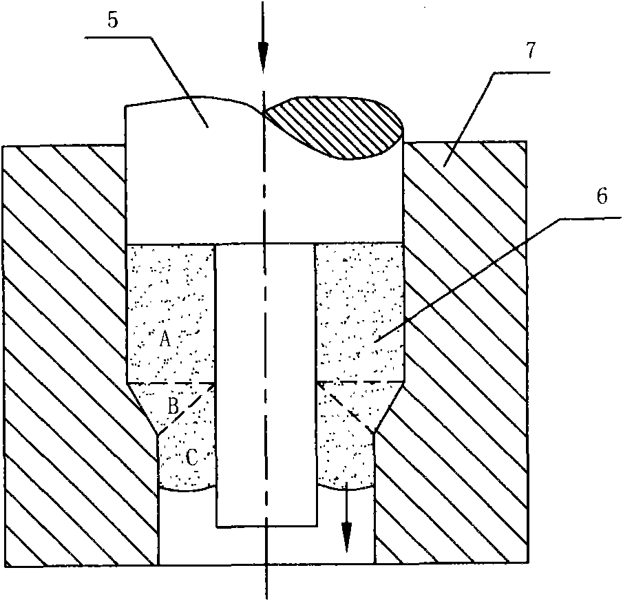
technical field [0001] The invention belongs to the field of metal material forming technology, and relates to a deep-hole extrusion forming technology of medium-carbon low-alloy structural steel. Background technique [0002] Medium-carbon low-alloy structural steels include: 40Cr, 42CrMo, 40MnB, 40CrMnMo, 35CrMo, 35CrMnSi, 40CrV, etc. At present, the extrusion forming methods of hollow parts of this kind of material mainly include back extrusion, such as figure 1 shown; positive extrusion, such as figure 2 Shown; Composite extrusion of positive and negative extrusion at the same time. Due to the high deformation resistance of the metal of this kind of material, limited by the strength and structure of the mold, the temperature of the extruded metal billet is higher than 800 ° C, which belongs to hot extrusion. Moreover, the surface quality of the inner hole of the hollow part is poor, and the extrusion The improvement of the metal structure and its mechanical propertie...

Claims


Application Information

Patent Timeline
IPC IPC(8): B21C23/02B21C25/02B21C26/00
Inventor 邓晓光
Owner 邓晓光
Learn More