Steel-concrete joint section structure of beams

A concrete combination and concrete technology, applied in bridges, bridge construction, bridge parts, etc., can solve problems such as difficult construction operations, poor fatigue resistance, complex processing and manufacturing, etc., to achieve clear and reasonable force, high torsional and bending rigidity , the effect of reasonable structure

Active Publication Date: 2010-09-15
TIANJIN MUNICIPAL ENG DESIGN & RES INST
View PDF9 Cites 20 Cited by
  • Summary
  • Abstract
  • Description
  • Claims
  • Application Information

AI Technical Summary

Problems solved by technology

[0015] The present invention provides a structure of the steel-concrete joint section of the beam, which solves the steel-concrete joint section in the prior art, considering comprehensive factors such as the structural force of the steel-concrete joint section of the beam, structural requirements

Method used


Image

  • Steel-concrete joint section structure of beams
  • Steel-concrete joint section structure of beams
  • Steel-concrete joint section structure of beams

Examples


Embodiment 1

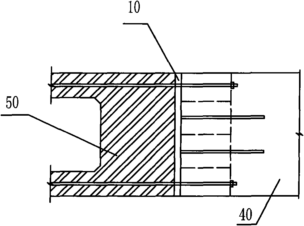
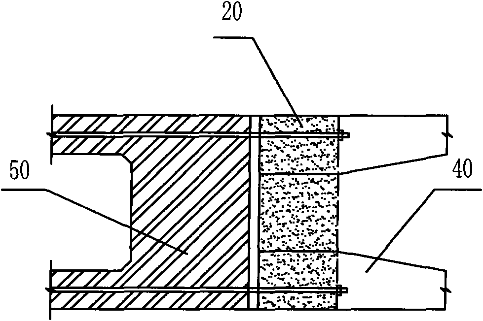
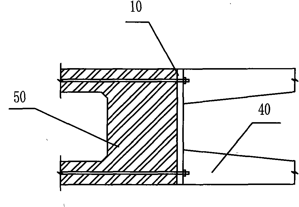
[0036] Such as figure 2 As shown, the structure of the steel-concrete bonded section of the beam of the present invention includes a steel beam 1 and a concrete beam 2, and a pressure bearing plate 3 is arranged at the junction of the steel beam 1 and the concrete beam 2, and the steel beam 1 It includes a steel beam top plate 11, a steel beam bottom plate 12 and a steel beam web 13; the concrete beam 2 includes a concrete web 21; the section profile of the steel beam 1 is consistent with the section profile of the concrete beam 2, The steel beam 1 is overlaid on the concrete beam 2, thereby forming a transition section 4 from the concrete beam to the steel beam, and the steel beam web 13 in the transition section 4 is inserted into the concrete beam web 21 to form a steel-concrete The composite section of , such as image 3 As shown; between the steel beam top plate 11 and the steel beam bottom plate 12 in the transition section 4, there are upper and lower closed compartme...

Embodiment 2

[0039] In the second embodiment, on the basis of the first embodiment above, the position of the transverse partition of the compartment is improved, that is, as Figure 6 As shown, in the second embodiment, the slope of the transverse partition 14 of the compartment 15 between the steel beam top plate 11 and the steel beam bottom plate 12 in the transition section 4 is 1:8˜1:15. Such as image 3 , Figure 4 and Figure 5 As shown, the structures of other parts in the second embodiment are the same as those in the first embodiment, and will not be repeated here.

[0040] In summary, the structure of the steel-concrete joint section of the beam of the present invention is compared with the prior art. The end bearing plate 3 adopts a 60mm thick integral steel plate that completely matches the cross section of the steel beam, which has high rigidity and small deformation. It can effectively ensure the uniform transmission of axial force and the anchoring requirements of prestr...


PUM


Abstract

The invention discloses a steel-concrete joint section structure of beams, which comprises a steel beam, a concrete beam and a bearing plate, wherein the steel beam is sheathed outside the concrete beam, thereby forming a transition section from the concrete beam to the steel beam; the steel beam web in the transition section is inserted into the concrete beam web to form a steel-concrete composite section; an upper and lower closed compartments are arranged in the transition section; the bearing plate is a steel plate of which the cross section being exactly matched with that of the steel beam; each contact site of the steel beam and the concrete beam in the transition section is provided with a shearing force toggle pin; the steel beam top plate and the steel beam bottom plate are respectively provided with a U-shaped ribbed stiffener; each U-shaped ribbed stiffener is welded with an pi-shaped ribbed stiffener; and the height of the pi-shaped ribbed stiffeners gradually increases from the steel beam side to the concrete beam side. The steel-concrete joint section of beams can be widely used in various composite beam bridges, such as continuous bridges, stayed-cable bridges, suspension bridges and arch bridges, and can solve the problems of complex process and manufacture, difficult construction operation and low fatigue resistance at the steel-concrete joint section.

Description

technical field [0001] The invention relates to a structure of a steel-concrete joint section, in particular to a structure of a steel-concrete joint section of a beam. Background technique [0002] Steel-concrete combined sections mainly appear in hybrid girder bridges. Hybrid girder bridges start from continuous girder bridges. When the ratio of side spans to mid-span lengths is small, the side spans use concrete beams with greater self-weight and stiffness, and the mid-span The use of lighter steel beams can avoid negative reaction forces at the end fulcrums of the side spans and balance the dead-load bending moment of the mid-span, and can also improve the rigidity and wind resistance stability of the structure during beam cantilever construction. The joint between the steel beam and the concrete beam mentioned above is the steel-concrete joint section. Due to economic rationality and technical reliability, steel-concrete bonded sections have been widely used in various...

Claims


Application Information

Patent Timeline
IPC IPC(8): E01D19/00
Inventor 曹景刘旭锴谢斌张强戴少雄孙东利何玉宝李伟李焱陆华臻张一卓
Owner TIANJIN MUNICIPAL ENG DESIGN & RES INST
Why Eureka
Try Eureka