Energy-dissipation beam column node of buckling-restrained bracing

An anti-buckling support and anti-buckling energy consumption technology, applied in the direction of earthquake resistance, building components, buildings, etc., can solve the problems of difficult post-earthquake repairs and limited building functions, and achieve easy post-earthquake repairs without affecting building functions , the effect of eliminating adverse effects

Inactive Publication Date: 2010-09-15
HARBIN INST OF TECH
View PDF7 Cites 14 Cited by
  • Summary
  • Abstract
  • Description
  • Claims
  • Application Information

AI Technical Summary

Problems solved by technology

[0003] The purpose of the present invention is to provide an energy-dissipating beam-column joint with anti-buckling support to solve the limitation of building use function caused by setting additional energy-dis

Method used


Image

  • Energy-dissipation beam column node of buckling-restrained bracing
  • Energy-dissipation beam column node of buckling-restrained bracing
  • Energy-dissipation beam column node of buckling-restrained bracing

Examples


specific Embodiment approach 1

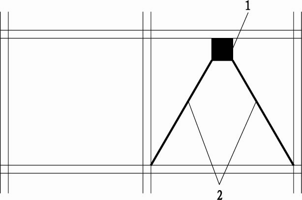
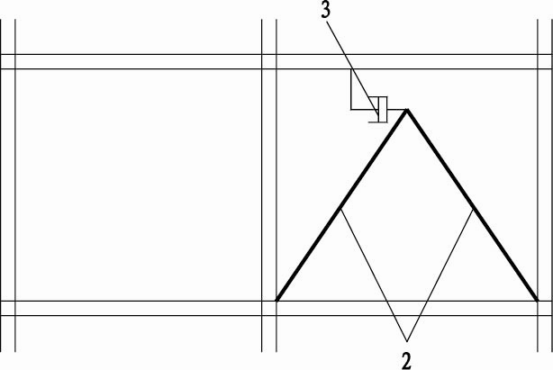
[0007] Specific implementation mode one: combine Figure 9~Figure 15 Note that the buckling-resistant braced energy-dissipating beam-column node 9 in this embodiment includes an I-shaped steel column 9-1 and an I-shaped steel beam 9-2; the buckling-resistant braced energy-dissipating beam-column node 9 in this embodiment also includes two steel Backing plate 9-3, two angle steel connectors 9-4 and two anti-buckling energy-dissipating support members; the two anti-buckling energy-dissipating support members consist of one anti-buckling energy-dissipating upper support member 9-5 and one anti-buckling energy-dissipating support member The lower supporting member 9-6 is composed of; two steel backing plates 9-3 are fixed on the outer surface of the same column flange 9-1-1 of the I-shaped steel column 9-1, and the two steel backing plates 9- 3 is arranged in one-to-one correspondence with two angle steel connectors 9-4, and the steel backing plate 9-3 is located between the I-sha...

specific Embodiment approach 2

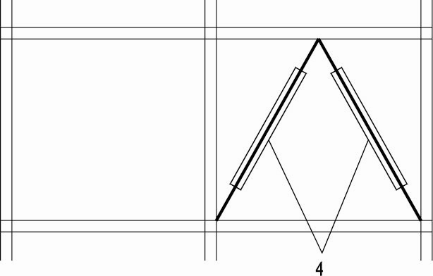
[0008] Specific implementation mode two: combination Figure 9~Figure 15 Explain that the anti-buckling energy-dissipating upper support member 9-5 of this embodiment consists of a T-shaped upper core plate 9-5-1, two T-shaped upper restraints 9-5-3 and two lateral upper limit members 9- 5-2 composition; each of the two side end faces of the long upper core plate 9-5-1-1 in the width direction of the T-shaped upper core plate 9-5-1 is processed with a lateral upper limit member 9-5- 2 The first grooves 9-5-1-2 that match in shape, each first groove 9-5-1-2 is equipped with a lateral upper limit piece 9-5-2, T-shaped upper core plate 9 The short upper core plate 9-5-1-3 of -5-1 and the column flange 9-1-1 of the I-shaped steel column 9-1 and the beam web 9-2-1 of the I-shaped steel beam 9-2 Tightly connected, one of the two T-shaped upper restraints 9-5-3 is arranged on the long upper core plate 9-5-1-1 of the corresponding T-shaped upper core plate 9-5-1 and the two side upwa...

specific Embodiment approach 3

[0009] Specific implementation mode three: combination Figure 9~Figure 15 Description, the column flange 9-1-1 of the I-shaped steel column 9-1 with the steel backing plate 9-3 of the present embodiment, two steel backing plates 9-3 and two angle steel connectors 9-4 between the two side plates of the two angle steel connectors 9-4 and the beam web 9-2-1 of the I-shaped steel beam 9-2, the buckling-resistant energy dissipation upper support member 9 -5 and between the column flange 9-1-1 of the I-shaped steel column 9-1 and the beam web 9-2-1 of the I-shaped steel beam 9-2 and the buckling-resistant energy dissipation lower support member 9-6 and The column flange 9-1-1 of the I-shaped steel column 9-1 and the beam web 9-2-1 of the I-shaped steel beam 9-2 are respectively fastened and connected by a plurality of high-strength bolts. With such setting, the connection is reliable, and the overall strength after connection is high. Others are the same as the first embodiment. ...


PUM


Abstract

The invention discloses an energy-dissipation beam column node of a buckling-restrained bracing, relating to a beam column node and aiming to solve the problems that an energy-dissipation damper which is additionally arranged to dissipate seismic energy results in the use functional limitation of buildings, a plastic hinge which is formed by the yielding of a structural member (a beam end) to dissipate the energy results in difficult seismic rehabilitation, and the like. In the invention, two steel base plates are fixed on the column flange of an I-steel column and positioned between the I-steel column and angle steel connectors, the column flange of the I-steel column is in fastening connection with the two base plates and the two angle steel connector, the two angle steel connectors are in fastening connection with a girder web of an I-steel girder, an upper buckling-restrained energy-dissipation bracing member is arranged close to the upper girder flange of the I-steel girder, a lower buckling-restrained energy-dissipation bracing member is arranged close to the lower girder flange of the I-steel girder, and the upper and the lower buckling-restrained energy-dissipation bracing members are respectively in fastening connection with the column flange of the I-steel column and the girder web of the I-steel girder. The invention is applied to the seismic resistance and earthquake proofing of building main bodies.

Description

technical field [0001] The invention relates to a beam-column joint, in particular to an energy-dissipating beam-column joint used in the field of building steel structures. Background technique [0002] Energy dissipation and shock absorption is currently one of the most effective means to reduce the seismic response of the main structure of a building under an earthquake and prevent it from collapsing in a major earthquake. There are two main methods of energy dissipation and shock absorption: one is to dissipate the seismic energy by installing additional energy dissipation dampers, and the location of the installation is generally limited between beam-column bays (such as Figure 1~3 shown), energy consumption is achieved through relative deformation between floors (energy dissipation components see Figure 1~3 The energy-dissipative shock absorber 1, the viscous damper 3 and the buckling-resistant energy-dissipative support damper 4); the other is to form a plastic hinge...

Claims


Application Information

Patent Timeline
IPC IPC(8): E04B1/58E04B1/98E04B1/24
Inventor 赵俊贤吴斌梅洋
Owner HARBIN INST OF TECH
Why Eureka
Try Eureka