Oil analysis method for diagnosing equipment failure

A technology for oil analysis and equipment failure, applied in particle size analysis, particle and sedimentation analysis, testing of machine/structural components, etc. problems such as low dispersion, to achieve the effect of improving automatic identification ability, rich information, and high definition

Inactive Publication Date: 2010-09-15
CHONGQING UNIV
View PDF3 Cites 8 Cited by
  • Summary
  • Abstract
  • Description
  • Claims
  • Application Information

AI Technical Summary

Problems solved by technology

[0004] Ferrography is currently the most important oil analysis method, but it has typical limitations: ①The operation process is very dependent on human experience; ②The degree of automation is low; ③The dispersion of wear particles is low, which increases the difficulty of extracting wear particle information
These limitations severely restrict the wide application of oil analysis technology in equipment fault diagnosis

Method used


Image

  • Oil analysis method for diagnosing equipment failure
  • Oil analysis method for diagnosing equipment failure
  • Oil analysis method for diagnosing equipment failure

Examples


Embodiment Construction

[0015] The present invention will be described in further detail below in conjunction with the accompanying drawings and specific embodiments.

[0016] An oil analysis method for equipment fault diagnosis includes the following steps:

[0017] 1) Arrange the nitrocellulose filter membranes with different filter pore sizes in order from large to small filter pore sizes, and let the oil to be tested flow through the nitrocellulose filter membranes in sequence from the large filter pore to the small filter pore.

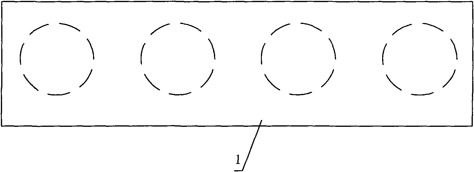
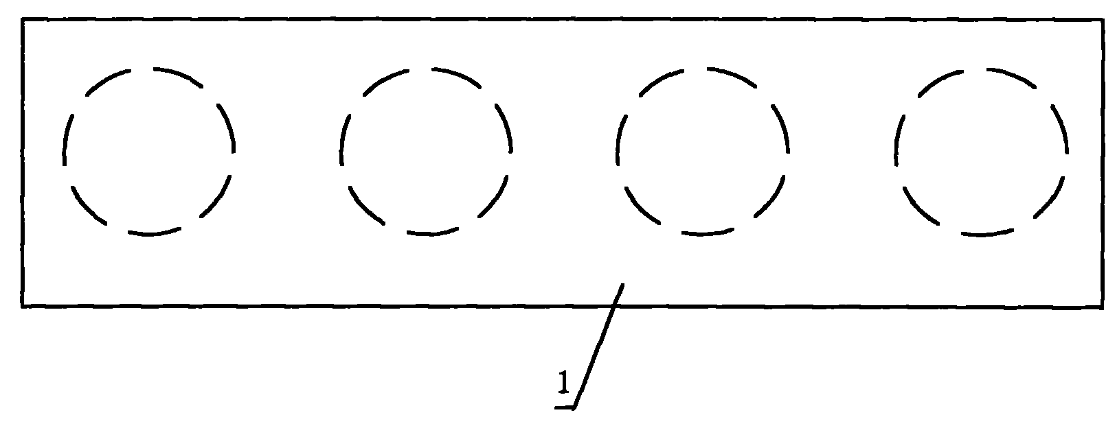
[0018] 2) Arrange the nitrocellulose filter membranes on the glass slide 1 in order according to the filter pore size from large to small.

[0019] 3) Dissolving the nitrocellulose filter membrane with an aqueous solution of dimethylformamide, leaving wear particles arranged in a particle size gradient on the slide glass 1 . like figure 1 As shown, according to the size of the filter pore size, as shown in the figure, there are four specifications of nitrocellulose fi...


PUM


Abstract

The invention discloses an oil analysis method for diagnosing an equipment failure. The method comprises the following steps of: 1) arranging cellulose nitrate filter membranes with different filter pore sizes in turn from large pore size to small pore size and allowing oil to be tested to flow through the cellulose nitrate filter membranes in turn; 2) arranging the cellulose nitrate filter membranes on a glass slide in turn from large pore size to small pore size; 3) dissolving the cellulose nitrate filter membranes with dimethyl formamide aqueous solution to leave wear particles arranged according to a particle size gradient on the glass slide; and 4) shooting and analyzing the wear particles on the glass slide to diagnose the equipment failure. The oil is filtered by using the cellulose nitrate filter membranes with different filter pore sizes and the wear particles on the glass slide are arranged according to different sizes, so that the method contributes to microscope observation and video camera shooting, realizes richer information content, higher definition and higher wear particle dispersion degree on an acquired wear map and contributes to realizing automatic recognition of the wear map and improving the accuracy of failure diagnosis.

Description

technical field [0001] The invention relates to a method for equipment fault diagnosis, in particular to an oil analysis method for equipment fault diagnosis. Background technique [0002] There are many methods of equipment fault diagnosis, each method has different sensitivity to different types of equipment, so the effect is not the same. The fault diagnosis technology based on oil analysis is especially suitable for large hydraulic equipment. Oil analysis technology is to obtain the information of the lubrication and wear state of the equipment by analyzing the performance change of the lubricant or working medium used in the equipment and the wear particles carried, so as to obtain the information of the lubrication and wear state of the equipment, evaluate the working condition of the equipment and predict the failure, and determine the cause of the failure, Type and location of technology. Usually, the oil analysis method for equipment fault diagnosis can benefit by...

Claims


Application Information

Patent Timeline
Patent Type & Authority Applications(China)
IPC IPC(8): G01N15/02G01M19/00G01M99/00
Inventor 任松姜德义杨春和李林
Owner CHONGQING UNIV
Why Eureka
Try Eureka