
Testing system and method for electronic control unit of automobile engine

A technology of automobile engine and electronic control unit, applied in the direction of internal combustion engine testing, electrical testing/monitoring, etc., can solve the problems of system equipment damage, threat to the safety of experimenters, and high testing costs

Inactive Publication Date: 2010-09-15
BEIJING INSTITUTE OF TECHNOLOGYGY
View PDF5 Cites 18 Cited by
  • Summary
  • Abstract
  • Description
  • Claims
  • Application Information

AI Technical Summary

Problems solved by technology

This will result in extremely high testing costs, and there are many uncertain factors that will damage the system equipment or even threaten the safety of the experimenters when performing bench experiments.
At the same time, when testing on the actual engine, due to the influence of various factors such as mechanical equipment and sensors, it is impossible to judge the quality of the ECU very well.
[0004] If the computer is completely used for virtual testing, it will cause insufficient realism. Even if the full virtual testing is carried out under the condition of ensuring realism, the cost of the developed system and technology will be too high.

Method used


Image

  • Testing system and method for electronic control unit of automobile engine
  • Testing system and method for electronic control unit of automobile engine
  • Testing system and method for electronic control unit of automobile engine

Examples


Embodiment Construction

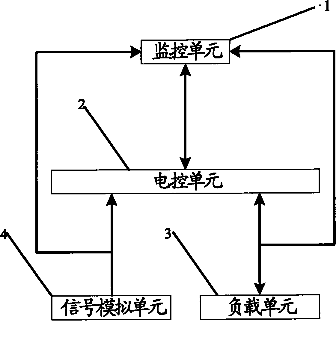
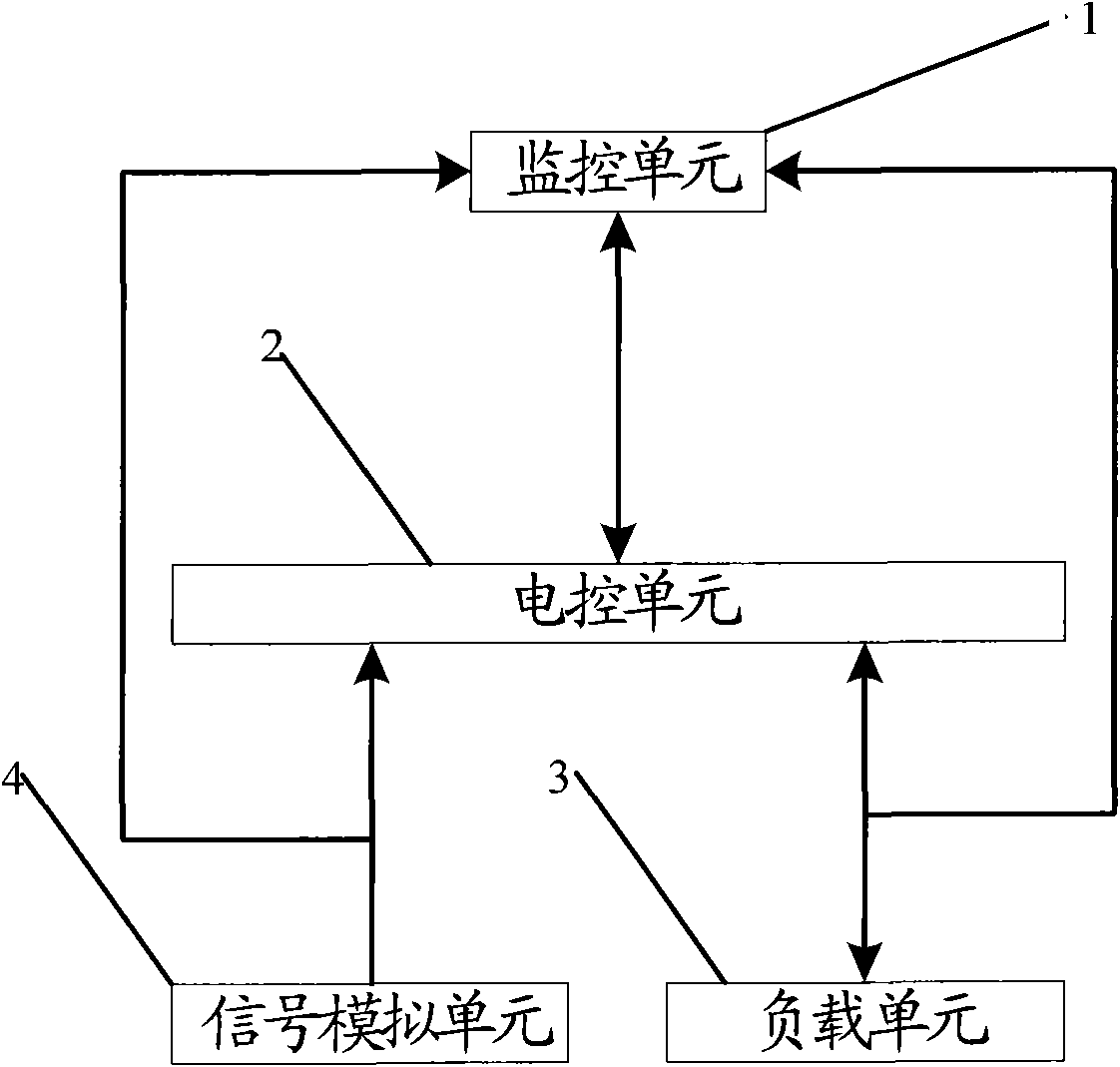
[0032] figure 1 It is a connection schematic diagram of the engine electronic control unit test system of the present invention, such as figure 1 As shown, the test system includes: a monitoring unit 1 , an electronic control unit (ECU) 2 , a load unit 3 and a signal simulation unit 4 . Among them, the electronic control unit 2 is at the core of the whole system.

[0033] The signal simulation unit 4 is connected to the electronic control unit 2 through the engine wiring harness, and is used to simulate the crankshaft signal and cam signal corresponding to the rotational speed generated when the engine is running according to the rotational speed input by the user, and send it to the electronic control unit 2 . Among them, the signal simulation unit 4 pre-stores the data of the rotational speed and the corresponding crankshaft signal and cam signal, and searches the data to obtain the corresponding crankshaft signal and cam signal after receiving the rotational speed input by...


PUM


Abstract

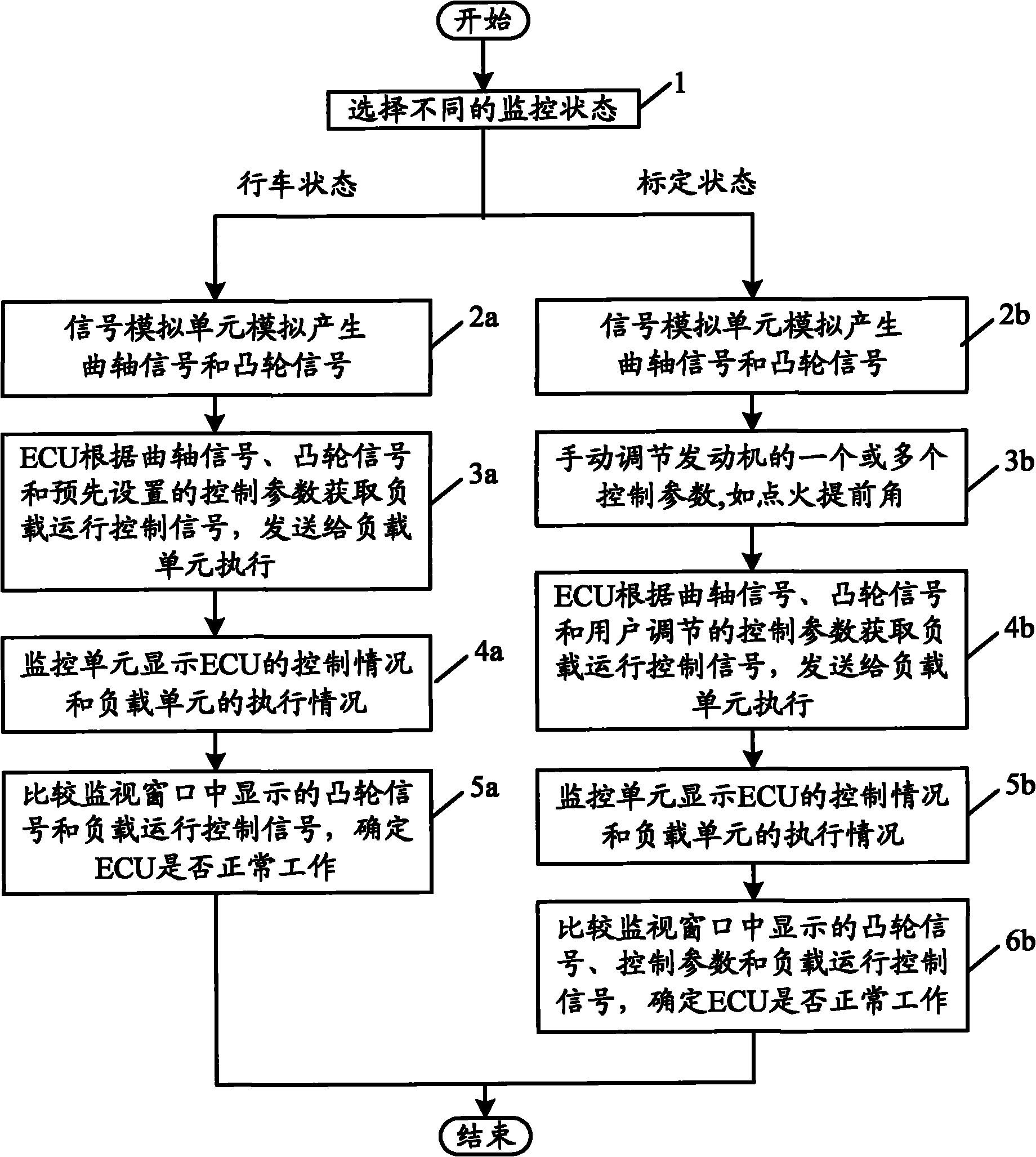
The invention discloses a testing system and a testing method for an electronic control unit of an automobile engine. The testing system comprises a signal simulation unit, an electronic control unit, a load unit and a monitoring unit, wherein the signal simulation unit is connected with the electronic control unit by a motor wiring harness and used for simulating cranking signals and cam signals generated when a motor operates according to an externally-input rotate speed and sending the cranking signals and the cam signals to the electronic control unit; the electronic control unit is used for acquiring on-load running control signals according to the cranking signals and the cam signals as well as control parameters and sending the on-load running control signals to the load unit; the load unit is an actual engine component, connected with the electronic control unit by the motor wiring harness and used for executing action according to the on-load running control signals sent by the electronic control unit; and the monitoring unit is used for monitoring the states of the electronic control unit and the load unit, and sending the control parameters input by the user to the electronic control unit in a calibration state. The testing system and the testing method can simultaneously carry out off-vehicle test on the ECU (electronic control unit) and use the actual engine component to compensate for the reality insufficiency existed of the traditional off-vehicle test so as to achieve the effect of carrying out reliable, low-cost and local test on the ECU (electronic control unit).

Description

technical field [0001] The invention relates to the technical field of automobile engines, in particular to a test system and a test method for an electric control unit of an automobile engine. Background technique [0002] There are two main ways to test the electronic control unit (ECU) of the automobile engine. One is to place the ECU on the actual engine and test it with a bench or vehicle test, and the other is to use a computer for virtual testing. [0003] The former requires that the ECU must be placed on the actual engine, all the input and output of the ECU are directly connected with the car, and all the data are measured data. This will result in extremely high testing costs, and when performing bench experiments, there are many uncertain factors that may damage system equipment or even threaten the safety of experimenters. At the same time, when testing on the actual engine, due to the influence of various factors such as mechanical equipment and sensors, it is...

Claims


Application Information

Patent Timeline
Patent Type & Authority Applications(China)
IPC IPC(8): G05B23/02G01M15/04
Inventor 刘兴华樊志强刘福水
Owner BEIJING INSTITUTE OF TECHNOLOGYGY
Learn More