Determination method of high voltage direct current converter commutation overlap angle

A high-voltage direct current, technology to determine the method, applied in the direction of the DC network circuit device, DC circuit can reduce harmonics/ripples, electrical components, etc., can solve the problem of reducing the accuracy of harmonic current calculations, and the duration of commutation and non-commutation is different Again the same, filter safety issues and other issues

Inactive Publication Date: 2012-07-04
ZHEJIANG UNIV
View PDF0 Cites 0 Cited by
  • Summary
  • Abstract
  • Description
  • Claims
  • Application Information

AI Technical Summary

Problems solved by technology

However, due to non-ideal factors in the actual system, such as negative sequence fundamental voltage, background harmonic voltage, asymmetry of the interval between the firing angle (turn-off angle) of the converter, the deviation of the converter transformer impedance, and the deviation of the converter ratio, each valve The commutation and non-commutation durations will no longer be the same, and the traditional method based on ideal conditions obviously cannot take into account the interaction of the above factors, which will lead to a reduction in the accuracy of harmonic current calculations, and may cause filtering under certain harsh conditions. server configuration security issue

Method used


Image

  • Determination method of high voltage direct current converter commutation overlap angle
  • Determination method of high voltage direct current converter commutation overlap angle
  • Determination method of high voltage direct current converter commutation overlap angle

Examples


Embodiment 1

[0055] In this example, the test working condition is unipolar single valve group (12 pulsation) metal circuit wiring method, such as Figure 8 As shown, the transmission power is 1250MW, the load level is 100%, and the DC current is the rated value of 3.125kA. The method for determining the commutation overlap angle is as follows:

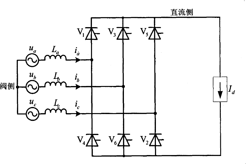
[0056] (1) According to the sequence of triggering moments of the six thyristors in the six-pulse rectifier bridge circuit, a working cycle of the six-pulse rectifier bridge circuit is divided into 6 commutation segments and 6 corresponding non-commutation segments, and each The commutation method of the commutation section;

[0057] The YY bridge and the YD bridge can be equivalently decoupled into a six-pulse full-wave rectifier unit through conversion ratio conversion and star-delta transformation. Since the YY bridge and the YD bridge have similarities in circuit structure, the equivalent circuit after decoupling is the same ,Such as figure...

Embodiment 2

[0119] 本实施例测试负荷水平是额定功率的10%,直流电流为0.3125kA,其他条件与实施例1所述一致,则按照实施例1的步骤可以如下结果:

[0120] 表7 换相重叠角结果(10%负荷水平)

[0121]

[0122]

[0123] 通过表7可以看出,低负荷水平下本发明方法与PSCAD / EMTDC仿真结果最大相对偏差为0.654%,最大绝对偏差为0.023°,仍然具有很高的精度;如果采用传统方法算得的结果为μ=3.642°,与PSCAD / EMTDC最大绝对偏差为0.403°,相对偏差接近10%,这误差本身已经比触发角偏差(±0.2°)还要大。

[0124] 通常以上对比可以看出,传统方法计算换相重叠角已经无法满足实际工程中各种工况,尤其是低负荷水平下的精度要求,进而导致谐波电流计算时换相段和非换相段确定出现较大误差,影响谐波计算结果,最终影响滤波器设计和配置,甚至可能出现安全问题。

[0125] 而PSCAD / EMTDC仿真虽然精确,但是整个模型从初始状态过渡到谐波稳定状态所需时间不少于1.8s,若要进行一个工程的滤波器设计,需要计算超过15000个运行方式,至少需要7.5 Hour. 而使用本发明方法对1个运行方式计算换相重叠角需要的时间少于0.01s,即使嵌入到谐波电流计算方法中整个运行时间也不会超过0.1s,对所有需要校核的运行工况遍历一次不会超过20分钟,具有很高的效率。


PUM


Abstract

The invention discloses a determination method of a high voltage direct current converter commutation overlap angle, aiming to solve the problem that a traditional method for calculating a commutation overlap angle can not take nonideal factors including background harmonics into consider to cause poor design performance of a wave filter. The method comprises the following steps of dividing the working period of a converter into six commutation sections and six non-commutation sections; establishing a differential equation to each commutation section by considering factors such as background harmonic interference, asymmetric fundamental voltage, asymmetric converter trigger angle distances, commutation impedance deviation and the like; and accurately calculating the commutation overlap angle. The invention efficiently enhances the calculation efficiency when ensuring the accuracy and can enhance the design quality of an alternating current converter.

Description

technical field [0001] The invention relates to the technical field of high voltage direct current transmission engineering, in particular to a method for determining the commutation overlap angle of a high voltage direct current converter. Background technique [0002] The structure of the rectifier station of the traditional two-terminal HVDC transmission system is shown as follows: figure 1 As shown, the transformer connected through YY and YD steps down the AC power on the AC busbar of the converter station (referred to as the grid side or AC side) into a lower voltage valve side AC power, and at the same time commutates the voltage for the upper and lower bridges Provide a phase difference of 30 degrees, and the converter containing the rectification circuit inside converts the three-phase AC power after step-down into DC side DC power, and the harmonics are filtered out by the smoothing reactance and DC filter system, and then passed through the high-voltage DC line D...

Claims


Application Information

Patent Timeline
Patent Type & Authority Patents(China)
IPC IPC(8): H02J1/00H02J1/02
Inventor 徐政薛英林李普明王峰屠卿瑞
Owner ZHEJIANG UNIV
Why Eureka
Try Eureka