High pressure pulse generating system for obtaining random-wave-form forced response and working procedure thereof

An arbitrary waveform, high-voltage pulse technology, applied in the direction of conversion equipment without intermediate conversion to AC, can solve the problems affecting the detection efficiency, the instrument is not easy to move, the transformer is bulky, etc., to achieve flexible data processing, improve efficiency, and simple system structure. Effect

Active Publication Date: 2013-03-06
PLA UNIV OF SCI & TECH
View PDF3 Cites 1 Cited by
  • Summary
  • Abstract
  • Description
  • Claims
  • Application Information

AI Technical Summary

Problems solved by technology

Some generating systems use transformers to boost the voltage. The transformers are not only large in size, but also have a certain frequency limit.
This kind of method will bring a lot of inconvenience to the detection of a large area, the instrument is not easy to move, and requires the supply of mains power, which affects the detection efficiency

Method used


Image

  • High pressure pulse generating system for obtaining random-wave-form forced response and working procedure thereof
  • High pressure pulse generating system for obtaining random-wave-form forced response and working procedure thereof
  • High pressure pulse generating system for obtaining random-wave-form forced response and working procedure thereof

Examples


Embodiment 1

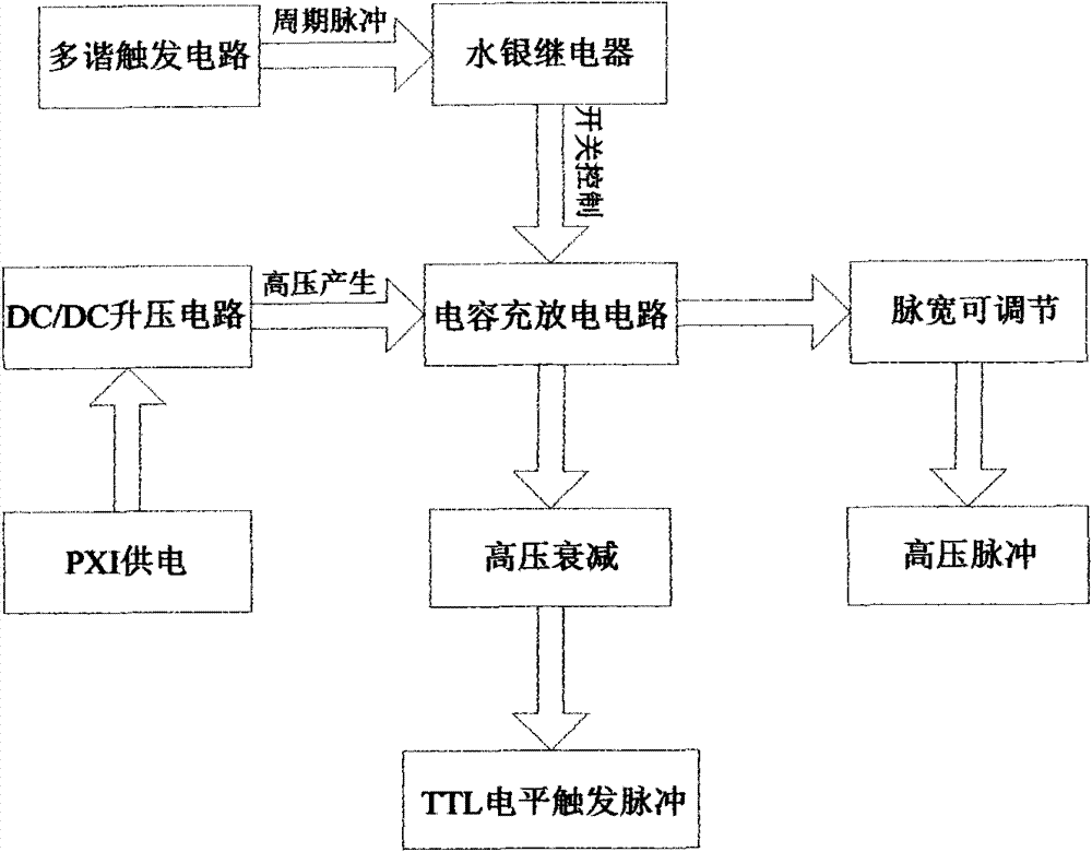
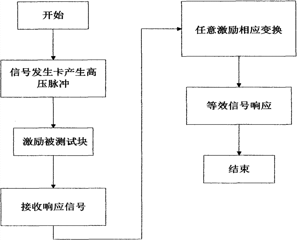
[0037] like figure 1 , figure 2 , image 3 Shown, the high-voltage pulse generation system that obtains arbitrary waveform excitation response of the present invention includes: 1) the high-voltage pulse generation circuit that is used to stimulate high-voltage pulse generation; 2) the PXI interface structure that is used to provide power; 3) is used to obtain direct current High-voltage DC / DC booster circuit; wherein all the above-mentioned circuits and structures are based on the PXI bus, and the high-voltage pulse generating circuit includes a capacitor charging and discharging circuit for generating high-voltage pulse signals with adjustable pulse width and synchronous trigger signals , used to control the discharge switch of the capacitor charging and discharging circuit and the multivibrator trigger circuit used to control the charging and discharging cycle. In this embodiment, the discharge switch used is a reasonably selected mercury relay with a sufficiently large ...

Embodiment 2

[0053] The system and method of embodiment 1 are compared with the effect of the prior art, such as Figure 4 As shown, the solid line represents the actual modulated wave response curve, that is, the excitation response of the pulse generated by the function generator and power amplifier to the structure under test. The dashed line represents the equivalent modulated wave response curve, ie, the response of the pulse generated by the system and method of the present invention to the excitation of the structure under test. Among them, the abscissa represents the number of sampling points, and the ordinate represents the relative amplitude of the curve. It can be seen from the figure that the actual modulated wave response curve basically coincides with the response curve generated by the system and method. That is, the system and method can completely replace other complex structures such as the existing function generator and power amplifier.


PUM


Abstract

The invention relates to a high pressure pulse generating system for obtaining random-wave-form forced response and a working procedure thereof; wherein the high pressure pulse generating system has the following components: 1) a high pressure pulse generating circuit for generating forced and detected structure signals and synchronous trigger signals, 2) a PXI interface structure for providing power and 3) a DC / DC booster circuit for obtaining DC high voltage. The generating system and working procedure of the invention has the following technical effects: 1) improving efficiency of nondestructive testing and lowering equipment cost; 2) obtaining multiple random-wave-form equivalent responses only through one excitation, more flexibly carrying out data processing on detection signals and improving data use effectiveness; 3) obtaining power and raising voltage through the PXI interface, facilitating compatible use with other computer systems and virtual instruments and enjoying simple system configuration.

Description

technical field [0001] The invention relates to a high-voltage pulse generation system and a working method for obtaining an excitation response of an arbitrary waveform, belonging to the field of ultrasonic nondestructive testing. Background technique [0002] Ultrasonic nondestructive testing (UT) is an important method of nondestructive testing of objects, which is applied to almost all industrial sectors. Compared with other conventional non-destructive testing technologies, it has the characteristics of wide range of detection objects, large detection depth, accurate defect location, high sensitivity, low cost, convenient work, fast speed, harmless to human body and convenient on-site use. [0003] When ultrasonic waves are used for non-destructive generation, two forms of step pulse broadband excitation and specific waveform narrowband excitation are generally used. Specific waveform narrowband excitation helps to improve the resolution of ultrasonic imaging system an...

Claims


Application Information

Patent Timeline
Patent Type & Authority Patents(China)
IPC IPC(8): H02M3/07
Inventor 石立华邵志学高成张琦
Owner PLA UNIV OF SCI & TECH
Why Eureka
Try Eureka