Efficient linear power amplifier circuit

A linear power and amplifying circuit technology, applied in the direction of power amplifiers, improving amplifiers to improve efficiency, etc., can solve problems such as unrealizable, inconvenient debugging, limiting the bandwidth of Doherty linear amplifying circuits, etc., to achieve simple structure, convenient debugging, and work efficiency high effect

Inactive Publication Date: 2010-09-15
SHANGHAI TUYUE ELECTRONICS CO LTD
View PDF3 Cites 12 Cited by
  • Summary
  • Abstract
  • Description
  • Claims
  • Application Information

AI Technical Summary

Problems solved by technology

However, the existing Doherty linear amplifying circuit has the following defects: 1) because the transmission line of 1 / 4 wavelength is used as impedance conversion, so in the case of relatively low frequency, the microstrip line of 1 / 4 wavelength will be too long. It affects the PCB layout (Layout) and circuit design, and sometimes it cannot even be realized; 2) Since the 1 / 4 wavelength microstrip line is not suitable for broadband systems, it limits the bandwidth of the existing Doherty linear amplifier circuit; 3) Now Doherty linear amplifier circuits are usually limited to single-stage amplification, and debugging is also very inconvenient

Method used


Image

  • Efficient linear power amplifier circuit
  • Efficient linear power amplifier circuit
  • Efficient linear power amplifier circuit

Examples


Embodiment Construction

[0026] The embodiments of the present invention will be described in further detail below in conjunction with the accompanying drawings, but the present embodiments are not intended to limit the present invention, and any similar structures and similar changes of the present invention should be included in the protection scope of the present invention.

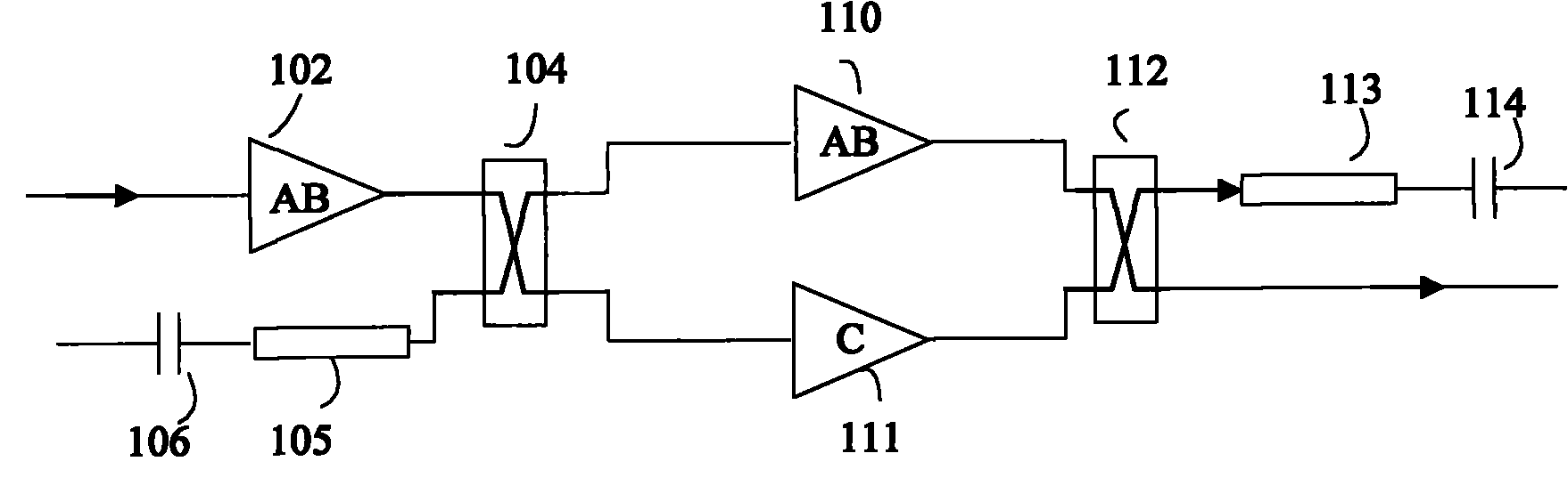
[0027] Such as figure 1 As shown, a high-efficiency linear power amplifier circuit provided by the first embodiment of the present invention includes a main amplifier 110 (carrier amplifier) ​​and an auxiliary amplifier 111 (peak amplifier), the main amplifier 110 is a class AB amplifier, and the auxiliary amplifier The amplifier 111 is a class C amplifier, characterized in that it also includes a front radio frequency bridge 104 and a rear radio frequency bridge 112;

[0028] An input end of the described front RF electric bridge 104 is connected to an external signal source through a driver stage amplifier 102, and the othe...


PUM


Abstract

An efficient linear power amplifier circuit relates to the technical field of energy amplification and solves the technical problems of facilitating debugging and increasing efficiency. The circuit comprises a main amplifier, an auxiliary amplifier, a front radio-frequency bridge and a back radio-frequency bridge, wherein one input end of the front radio-frequency bridge is connected with an external signal source, the other input end is in serial connection with a pre-microstrip line and a pre-capacitor in turn, the two output ends are separately connected with the input end of the main amplifier and the input end of the auxiliary amplifier; the output ends of the main amplifier and auxiliary amplifier are separately connected with the two input ends of the back radio-frequency bridge; and one output end of the back radio-frequency bridge is used as the signal output end, and the other output end is in serial connection with a post-microstrip line and a post-capacitor. The circuit provided by the invention can provide wider bandwidth.

Description

technical field [0001] The invention relates to power amplification technology, in particular to a high-efficiency linear power amplification circuit technology. Background technique [0002] RF power amplifier circuits are widely used in various wireless systems. In order to improve the utilization of spectrum resources, modern wireless systems use complex structures and modulation methods, such as QPSK, QAM, QAM16, QAM64 and other modulations in 3G and OFDM communications. In these wireless systems, the peak-to-average ratio of the signal reaches 10dB or even higher. In order to limit the spurious component of the signal carrier to meet the requirements of the system specification, it is necessary to use a linear power amplifier circuit in these systems. [0003] Such as Figure 5 As shown, in the existing linear power amplifying circuit, the class AB balanced linear power amplifying circuit includes a driving stage amplifier 502, a front RF bridge 504, a rear radio freque...

Claims


Application Information

Patent Timeline
Patent Type & Authority Applications(China)
IPC IPC(8): H03F3/20H03F1/02
Inventor 杜承法
Owner SHANGHAI TUYUE ELECTRONICS CO LTD
Why Eureka
Try Eureka