
LED (Light Emitting Diode) white light receiving and amplifying circuit for communication

A technique of amplifying circuits and circuits, applied in electromagnetic receivers, electrical components, electromagnetic wave transmission systems, etc., can solve problems such as unsatisfactory waveforms, restricted transmission rates, slow light intensity changes, etc., to achieve easy waveform demodulation and stable received signals , fast response effect

Inactive Publication Date: 2010-09-15
INST OF SEMICONDUCTORS - CHINESE ACAD OF SCI
View PDF4 Cites 1 Cited by
  • Summary
  • Abstract
  • Description
  • Claims
  • Application Information

AI Technical Summary

Problems solved by technology

The optical signals detected by the traditional mature optical receiving circuit are mostly low-frequency, and the light intensity changes slowly. In the high-frequency stage, especially in an open environment, the photodetector device is more sensitive to the background light of the environment, and the waveform is easy to be disordered. The optical receiving circuit cannot meet the waveform restoration and final demodulation, which has become a bottleneck restricting the transmission rate and needs to be solved urgently.

Method used


Image

  • LED (Light Emitting Diode) white light receiving and amplifying circuit for communication
  • LED (Light Emitting Diode) white light receiving and amplifying circuit for communication
  • LED (Light Emitting Diode) white light receiving and amplifying circuit for communication

Examples


Embodiment Construction

[0017] In order to make the object, technical solution and advantages of the present invention clearer, the present invention will be described in further detail below in conjunction with specific embodiments and with reference to the accompanying drawings.

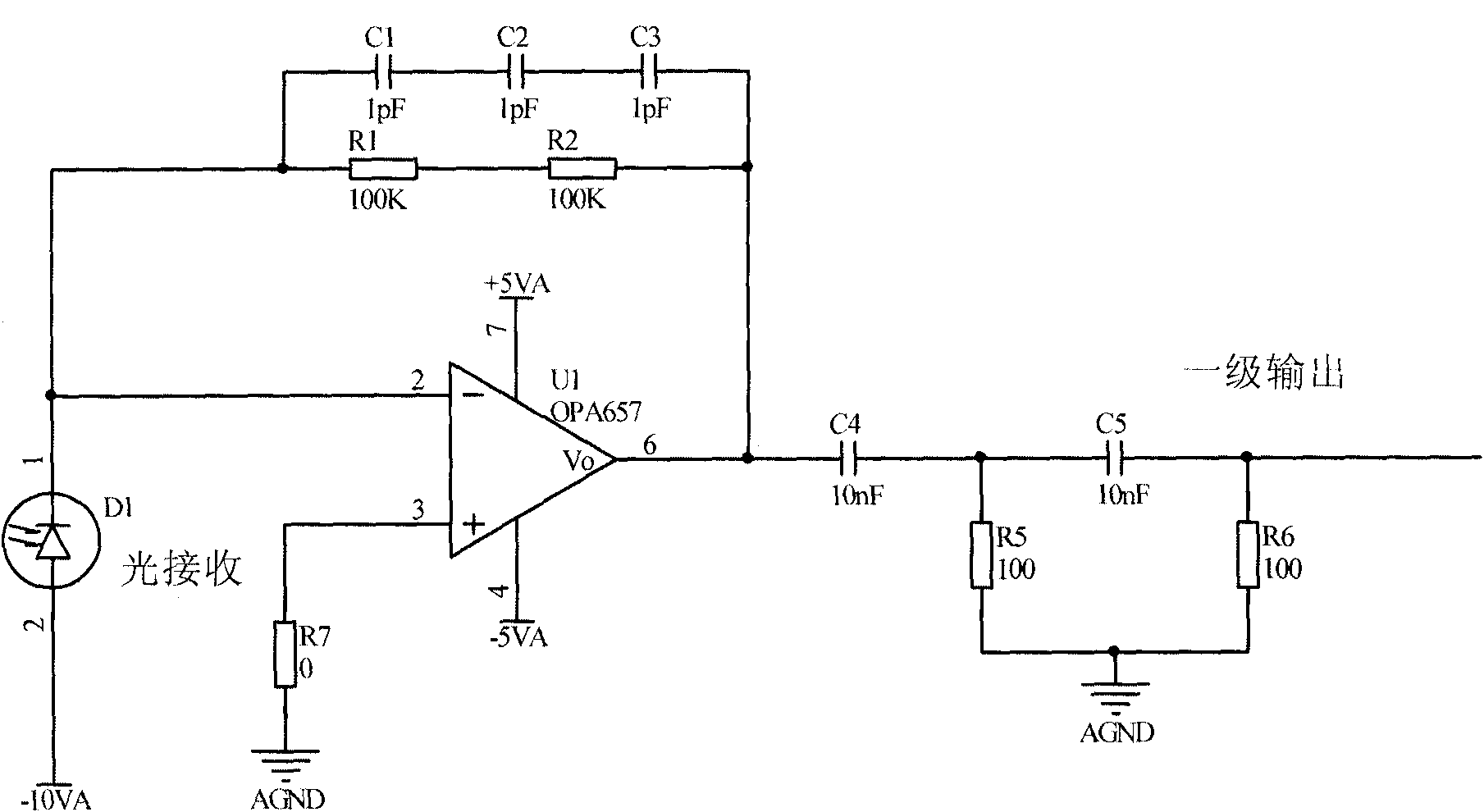
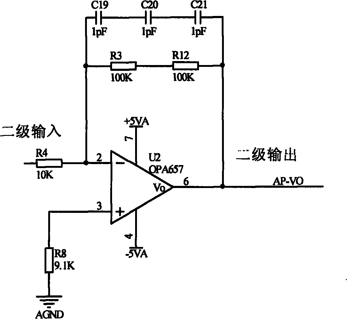
[0018] Such as figure 1 as shown, figure 1 It is a schematic diagram of an LED white light receiving and amplifying circuit for communication provided by the present invention. The circuit includes a receiving and amplifying circuit and an AGC circuit. The receiving and amplifying circuit receives the LED light signal, amplifies the LED light signal and outputs it to the AGC circuit. The AGC circuit controls the gain compensation of the LED light signal, which is finally output from the AGC-Vo terminal of the AGC circuit.

[0019] Wherein, the receiving amplifying circuit is composed of an optical detector, two high-bandwidth operational amplifiers, a DC blocking capacitor, a current limiting resistor and a feedback resi...


PUM


Abstract

The invention discloses an LED (Light Emitting Diode) white light receiving and amplifying circuit for communication. The circuit comprises a receiving and amplifying circuit and an AGC (Automatic Gain Control) circuit, wherein the receiving and amplifying circuit receives an LED light signal and amplifies and outputs the LED light signal to the AGC circuit; the gain compensation of the LED light signal is controlled by the AGC circuit; and finally, the LED light signal is output by the AGC-Vo end of the AGC circuit. The LED white light receiving and amplifying circuit for communication has functions of high magnification factor, gain compensation, and the like, stable signal receiving, high precision and high response speed and is easy for waveform demodulation.

Description

technical field [0001] The invention relates to a light receiving circuit, in particular to an LED white light receiving and amplifying circuit for communication. Background technique [0002] To realize the optical receiving circuit, the most reliable method at present is to convert the optical signal into an electrical signal by using an optoelectronic device, and then amplify and output it. The optical signals detected by the traditional mature optical receiving circuit are mostly low-frequency, and the light intensity changes slowly. In the high-frequency stage, especially in an open environment, the photodetector device is more sensitive to the background light of the environment, and the waveform is easy to be disordered. None of the optical receiving circuits can meet the waveform restoration and final demodulation, which has become a bottleneck restricting the transmission rate and needs to be solved urgently. Contents of the invention [0003] (1) Technical probl...

Claims


Application Information

Patent Timeline
Patent Type & Authority Applications(China)
IPC IPC(8): H04B10/06H04B10/60
Inventor 施安存郑国段靖远王锐金钰
Owner INST OF SEMICONDUCTORS - CHINESE ACAD OF SCI
Learn More