Base band power statistic-based standing wave detecting system and method for radio frequency remote system

A baseband power and standing wave detection technology, which is applied in the transmission system, synchronization/start-stop system, measurement device, etc., can solve the problems of affecting accuracy, unfavorable realization, and limiting accuracy, so as to ensure linear consistency, provide detection accuracy, The effect of reducing hardware costs

Active Publication Date: 2010-09-15
COMBA TELECOM SYST CHINA LTD
View PDF6 Cites 39 Cited by
  • Summary
  • Abstract
  • Description
  • Claims
  • Application Information

AI Technical Summary

Problems solved by technology

The problem with this solution is that the test accuracy is not high. The higher the accuracy, the larger the storage table, which is not conducive to the implementation
The problem with this solution is that in order to detect the forward power and reverse power, the feedback channel and AD conversion circuit must be specially added. Different frequency gain will also affect its accuracy
In addition, there are no components used for temperature compensation in the feedback link in this scheme, so the gain of the feedback link changes with temperature must also be obtained by looking up the temperature gain table, which will also limit its accuracy; and the accuracy The higher the requirements, the larger the lookup table, which is also not conducive to realization; at the same time, in order to obtain the temperature value, a temperature sensor must be added, which will inevitably increase the product cost

Method used


Image

  • Base band power statistic-based standing wave detecting system and method for radio frequency remote system
  • Base band power statistic-based standing wave detecting system and method for radio frequency remote system
  • Base band power statistic-based standing wave detecting system and method for radio frequency remote system

Examples


Embodiment

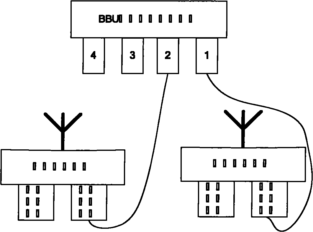
[0040] figure 1 Describes the position of the remote radio system in the entire wireless network. The main function of the remote radio system is to deframe the downlink baseband data transmitted by the BBU (baseband processing unit) through the optical fiber to restore the carrier data, and then undergo subsequent filtering and frequency conversion And power amplification and other processing, and finally transmitted to the user terminal through the coverage antenna; the uplink is to receive the wireless signal sent by the user terminal, after down-conversion filtering, AD sampling digitization, and finally the frame is packaged and transmitted to the BBU through the optical fiber. The networking mode can support star, daisy chain, ring or mixed networking of multiple networking modes.

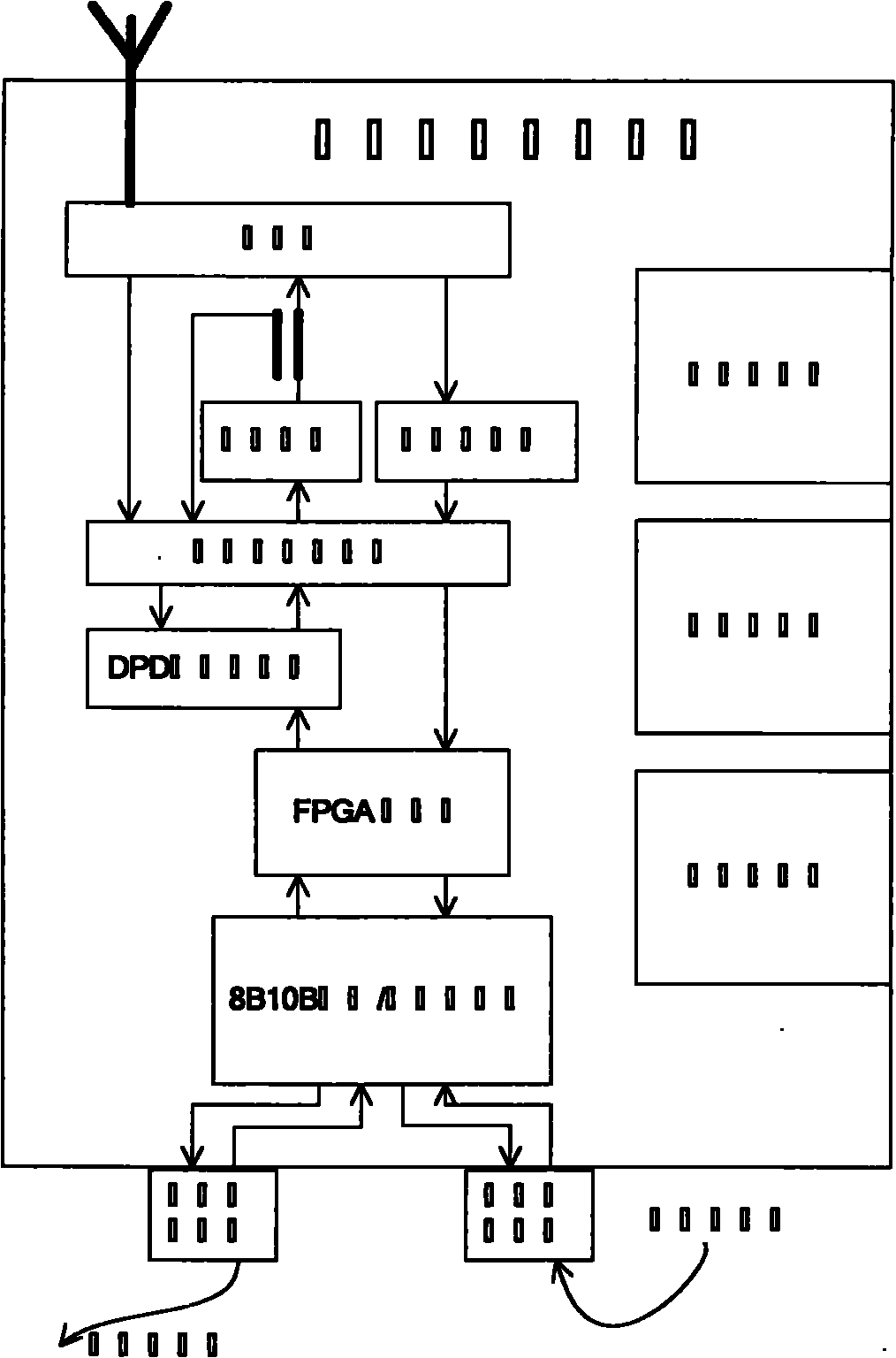
[0041] figure 2 Described is the structural block diagram of the whole remote radio system. The whole radio remote system is mainly composed of power supply subsystem, clock subsystem, mon...


PUM


Abstract

The invention relates to a standing wave detecting system and a standing wave detecting system method for a radio frequency remote system, which fully use a hardware module of a DPD processing subsystem in the radio frequency remote system and count an average power by adopting a base band power statistic module, so that the precision of the standing wave detection is improved and the cost of the standing wave detection is reduced. The standing wave detecting system comprises a switch, a forward power feedback link, a backward power reading link, and a radio frequency feedback link, an analogue digital converter, a digital down-conversion module, the base band power statistic module and a monitoring subsystem, which are connected sequentially. The switch is connected with the forward power feedback link, the backward power reading link, and the radio frequency feedback link respectively; the base band power statistic module is used for performing statistic on the forward power feedback link and the backward power reading link and then computing the average power under the control of the monitoring subsystem; and the monitoring subsystem is used for computing a standing-wave ratio according to the average power.

Description

technical field [0001] The invention relates to the field of remote radio system of mobile communication technology, in particular to a system and method for detecting standing wave ratio. Background technique [0002] The standing wave ratio is a very important radio frequency parameter in the field of wireless communication, which is used to measure the size of the standing wave. The standing wave is caused by the impedance mismatch of the transmission link, that is, the signal energy transmitted by the power amplifier module is not completely transmitted, and a part of it is reflected back and superimposed with the field strength of the transmitted signal to form a standing wave. Standing waves will be introduced when the link connection is not strong enough to cause poor contact, the link disconnection caused by natural disasters and human factors affects the link impedance mismatch, or the link design itself has poor impedance matching. The existence of standing waves ...

Claims


Application Information

Patent Timeline
Patent Type & Authority Applications(China)
IPC IPC(8): H04B17/00H04L25/49G01R27/06H04W24/08
Inventor 欧阳珍学龚伟潘晓明罗晟
Owner COMBA TELECOM SYST CHINA LTD
Why Eureka
Try Eureka