Capacitance type minitype silicon microphone and preparation method thereof

A silicon microphone and capacitive technology, applied in the field of silicon microphone and its preparation, can solve the problems of extremely high process control requirements, increased process complexity, poor repeatability, etc., and achieve easy process, flexible design, and high yield Effect

Active Publication Date: 2013-01-02
无锡芯感智半导体有限公司
View PDF0 Cites 0 Cited by
  • Summary
  • Abstract
  • Description
  • Claims
  • Application Information

AI Technical Summary

Problems solved by technology

[0005] At present, there are usually two ways to improve the residual stress of the diaphragm. One is to use an additional process and annealing. This method requires extremely high process control and the repeatability is not very good; the other is through structural adjustment, such as manufacturing Free membrane structure, but the fabrication of this structure will lead to an increase in process complexity, and it may be necessary to add a multi-step process to control the diaphragm
Realizing a rigid back electrode is also a major difficulty in the microphone manufacturing process. At present, there are two main methods to solve it. One is to make a thick back electrode, but it is difficult to obtain the required thick back electrode through conventional deposition processes; One method is to improve the rigidity of the back plate through structural adjustment, but it also increases the complexity of the process

Method used


Image

  • Capacitance type minitype silicon microphone and preparation method thereof
  • Capacitance type minitype silicon microphone and preparation method thereof
  • Capacitance type minitype silicon microphone and preparation method thereof

Examples


Embodiment Construction

[0025] The present invention will be further described below in conjunction with specific drawings and embodiments.

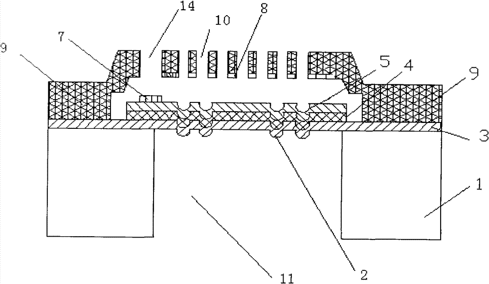
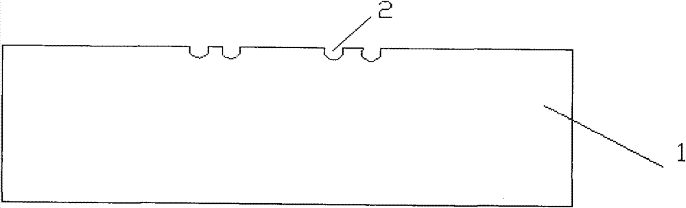
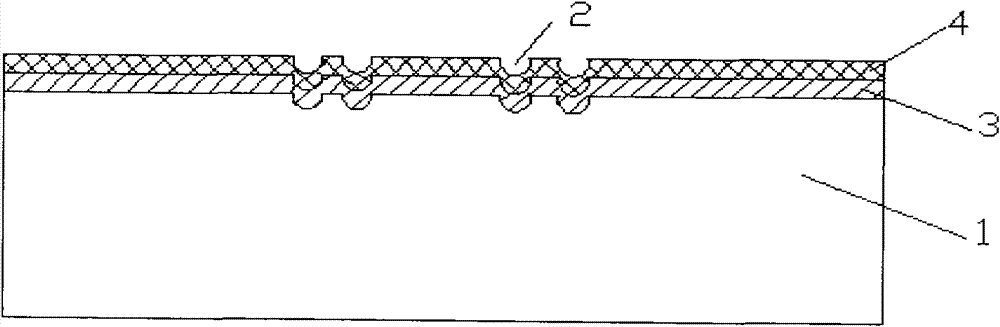
[0026] Such as Figure 1 to Figure 11 As shown: the present invention includes a substrate 1, a film groove 2, an insulating support layer 3, an insulating layer 4, a diaphragm 5, a sacrificial layer 6, a diaphragm electrode 7, a back plate 8, an insulating material layer 9, an acoustic hole 10, Acoustic cavity 11, movable beam 12, etching hole 13 and metal injection hole 14

[0027] Such as figure 1 with Figure 10 As shown: the surface of the substrate 1 is concavely provided with a film groove 2 , and the substrate 1 corresponds to the surface on which the film groove 2 is provided with a deposited diaphragm 5 . The diaphragm 5 is conductive polysilicon or an insulating support layer 3 , an insulating layer 4 and a conductive layer form a composite structure. When the vibrating film 5 is an insulating support layer 3, the insulating layer 4 and the condu...


PUM


Abstract

The invention relates to a capacitance type minitype silicon microphone and a preparation method thereof. The capacitance type minitype silicon microphone comprises a base plate; a vibrating diaphragm is deposited in the central area of the base plate; an insulating material layer is also deposited on the surface of the base plate, which corresponds to an installed base plate; the insulating material layer covers the surfaces of the base plate and the vibrating diaphragm, and a cavity is formed between the insulating material layer and the vibrating diaphragm; the inner wall of the insulatingmaterial layer, which corresponds to the vibrating diaphragm, is provided with fixedly connected back pole plates, and a capacitance structure is formed by the back pole plates and the vibrating diaphragm; the outer wall of the insulating material layer, which corresponds to the vibrating diaphragm, is provided with a plurality of sound holes, and the sound holes are communicated with the cavity formed between the insulating material layer and the vibrating diaphragm; the lower part of the base plate, which corresponds to an installed vibrating diaphragm, is provided with a sound cavity, and the depth of the sound cavity extends from the surface of the base plate, which corresponds to the other end of the installed vibrating diaphragm, to the vibrating diaphragm. The invention has low manufacturing cost, high finished product ratio and easy process operation and meets the requirements for small dimension.

Description

technical field [0001] The invention relates to a silicon microphone and a preparation method thereof, in particular to a capacitive micro-silicon microphone and a preparation method thereof, in particular to a micro-silicon microphone utilizing MEMS technology and a preparation method thereof. Background technique [0002] MEMS (Micro-Electro-Mechanical Systems) technology is a high-tech that has developed rapidly in the past few years. Compared with traditional counterparts, MEMS devices have obvious advantages in terms of volume, power consumption, and weight. The advanced semiconductor manufacturing process can realize the batch manufacturing of MEMS devices, can control the production cost extremely well, and improve the consistency of the devices. For the current MEMS products, accelerometers, pressure sensors, gyroscopes, micromirrors, silicon microphones, etc. have all been mass-produced and have occupied a certain share in the corresponding market. [0003] Silicon...

Claims


Application Information

Patent Timeline
Patent Type & Authority Patents(China)
IPC IPC(8): H04R19/04H04R31/00
Inventor 刘同庆沈绍群
Owner 无锡芯感智半导体有限公司
Why Eureka
Try Eureka