

Power control device of a power network of an electrochemical coating facility
A current control and electrochemical technology, applied in the direction of electrolytic components, electrolytic process, cells, etc., can solve the problems of increasing the cost of coating equipment, and achieve the effect of reducing phase shift reactive power and reducing amplitude
- Summary
- Abstract
- Description
- Claims
- Application Information
AI Technical Summary
Problems solved by technology
Method used
Image

Examples
Embodiment Construction
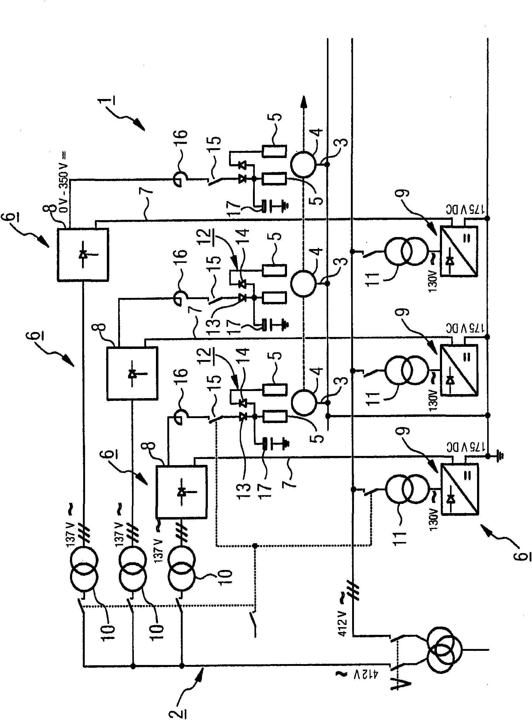
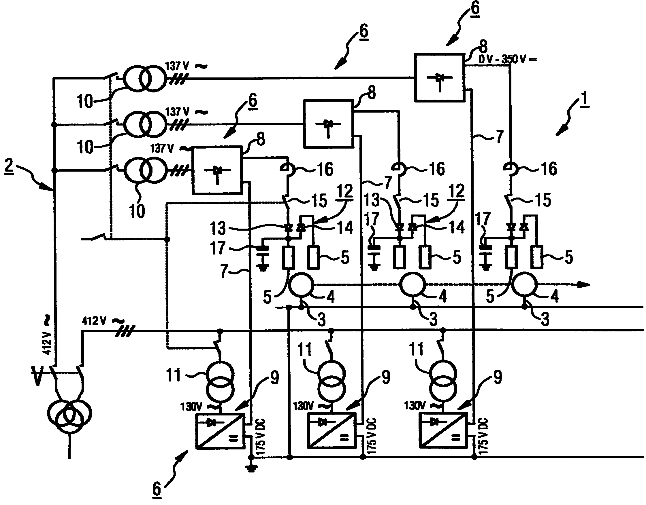
[0037] exist figure 1 The circuit diagram of the current control device 1 of the grid 2 of the electrochemical coating plant is schematically shown in .
[0038] The potential matching represented by the coating process takes into account the matching of the secondary voltages of the insulating transformers. This makes it possible to additionally optimize the reactive power component in the drive network.
[0039] The grid 2 comprises a plurality of cathodes 3 which are electrically conductively connected to several objects 4 to be coated, and a plurality of anodes 5 each grouped in pairs. The cathode 3 is fed together with the object to be coated 4 and the anode 5 into a dipping bath containing a metal salt solution.
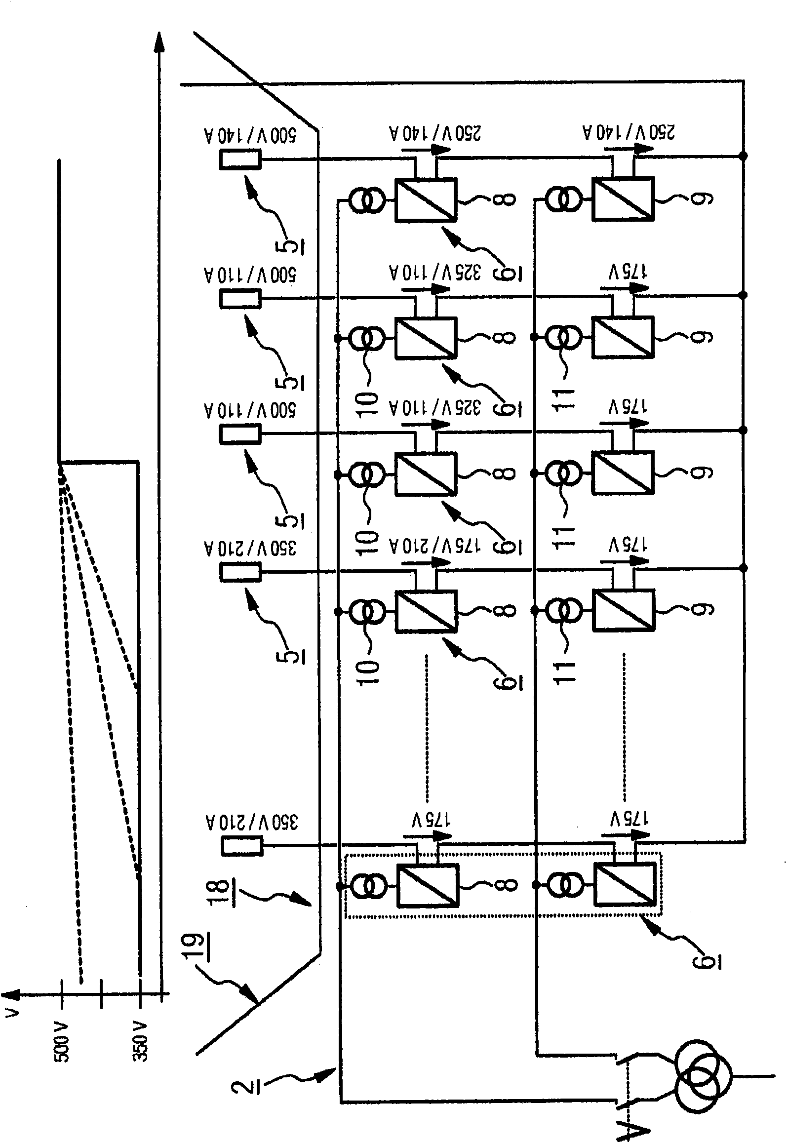
[0040] The current control device 1 comprises several control modules 6 each having a series circuit 7 of a controlled transistor bridge circuit 8 and an uncontrolled diode bridge circuit 9 . The transistor bridge 8 and the diode bridge 9 are connected on th...
PUM
 Abstract
Description
Claims
Application Information