Milling blade, milling cutter and installation method for milling cutter

A technology for milling cutters and inserts, which is applied in the direction of milling cutters, manufacturing tools, milling machine equipment, etc., can solve problems such as the limitation of efficient cutting capacity, the inability to effectively discharge chips, and the unsatisfactory chip breaking effect, so as to improve the cutting resistance. Effect of processing surface quality and reducing impact

Inactive Publication Date: 2010-09-22
ZHUZHOU CEMENTED CARBIDE CUTTING TOOLS CO LTD
View PDF6 Cites 5 Cited by
  • Summary
  • Abstract
  • Description
  • Claims
  • Application Information

AI Technical Summary

Problems solved by technology

Although the structure of this kind of continuous straight edge and intermittent straight edge can reduce a certain cutting force, its chip breaking effect is not ideal, especially in high-efficiency cutting, due to the increase in chip removal requirements per unit time, and this Because the straight edge part of the blade cannot break chips in time, the chips cannot be effectively discharged, and the blade is easy to wear and vibrate, and the efficient cutting ability is limited to a certain extent.

Method used


Image

  • Milling blade, milling cutter and installation method for milling cutter
  • Milling blade, milling cutter and installation method for milling cutter
  • Milling blade, milling cutter and installation method for milling cutter

Examples


Embodiment Construction

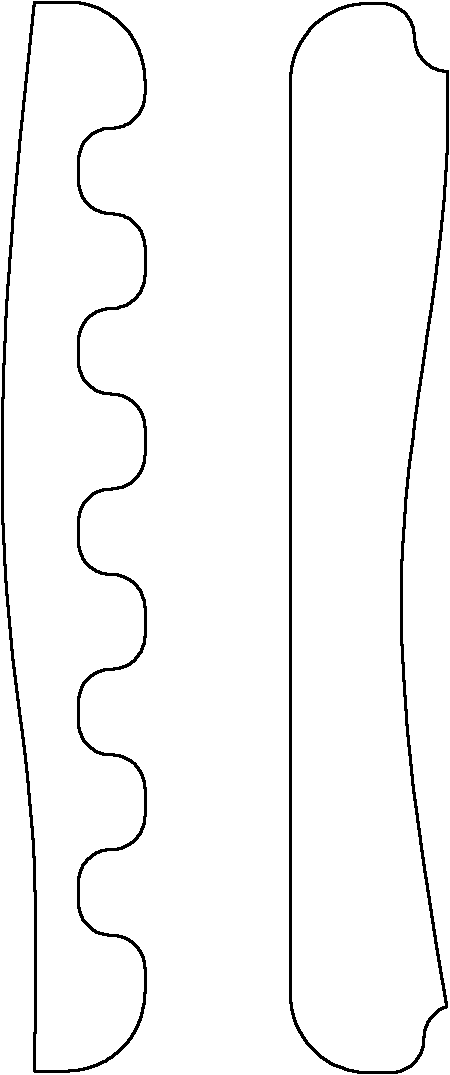
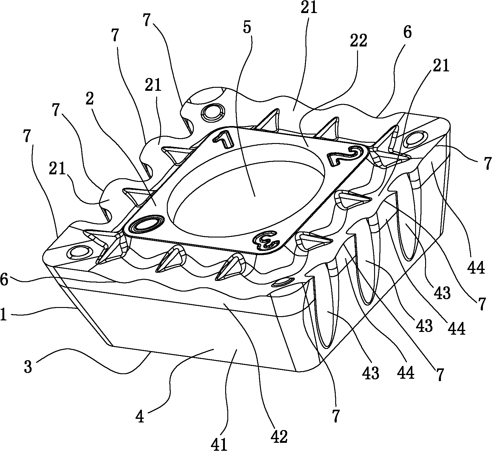
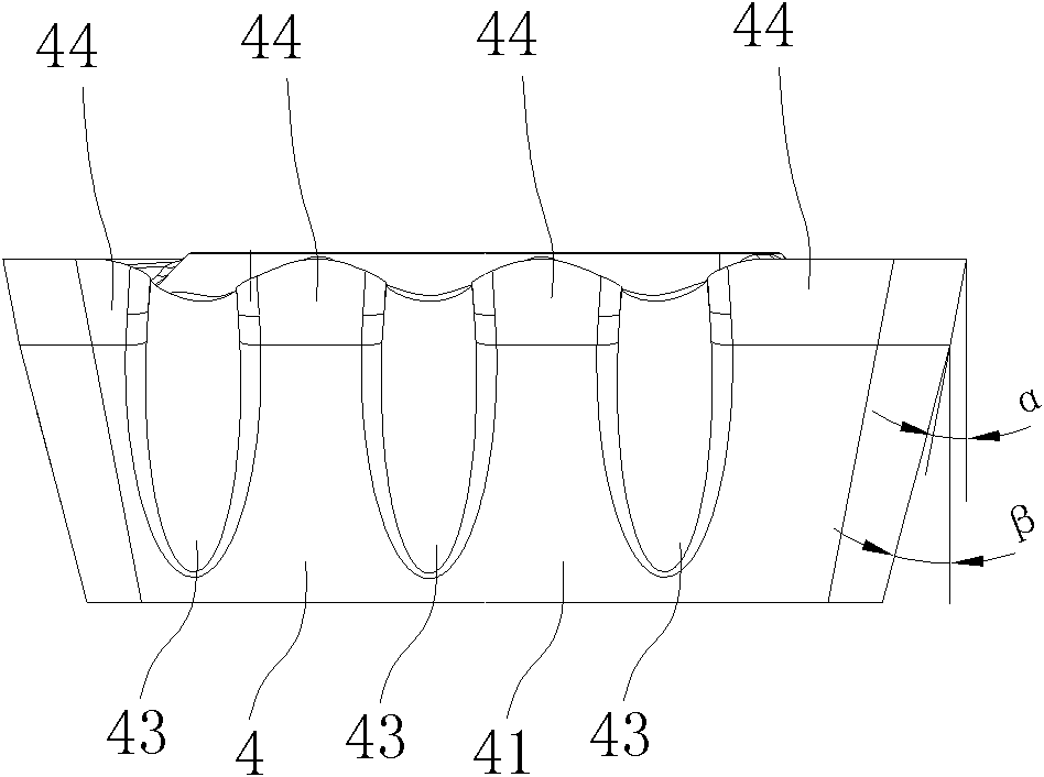
[0029] Figure 2 to Figure 4 A milling insert embodiment of the present invention is shown, the insert includes a polygonal plate-shaped insert body 1, the insert body 1 is surrounded by an upper surface 2, a lower surface 3 and a plurality of side surfaces 4 connecting the upper and lower surfaces, the insert The center of the body 1 is provided with a blade center hole 5 for installation and positioning. Each side 4 has a relief surface 41 and a flank surface. The flanks correspond to the rake face 21 one by one, and the rake face 21 is located at the periphery of the supporting surface 22. The flank face of one side 4 in the plurality of sides 4 is a planar flank 42, and the planar flank 42 The corresponding rake face 21 is a wave surface, and the planar flank face 42 intersects with the wave-shaped rake face 21 to form a continuous wave edge 6. The wave structure of the cutting edge can increase the distance between the insert rake face 21 and the workpiece. The contact a...


PUM


Abstract

The invention discloses a milling blade. The milling blade comprises a blade body in the shape of a polygonal plate, wherein the blade body is enclosed by an upper surface, a lower surface and a plurality of side faces connecting the upper surface and the lower surface; the centre of the blade body is provided with a blade centre hole for installation and positioning; each side face is provided with a rear gap surface and a rear cutter surface; the rear gap surface is adjacent to the lower surface; the upper surface is provided with a front cutter surface in one-to-one correspondence with each rear cutter surface; the rear cutter surface of at least one side face is a planar rear cutter surface; the front cutter surface corresponding to the planar rear cutter surface is a wavelike surface; and the planer rear cutter surface is crossed with the wavelike planar front cutter surface to form a continuous wavelike blade. The milling blade has the advantages of increasing the contact area of the front cutter surface and a workpiece, reducing the impact when the workpiece is cut, reducing the cutting force, improving the chip breaking and cutting capacity, reducing the wearing and meeting high-efficiency cutting requirement. The invention also discloses a milling cutter provided with the milling blade and an installation method for the milling cutter.

Description

technical field [0001] The invention relates to milling processing technology, in particular to a milling insert, a milling tool equipped with the insert and an installation method of the milling tool. Background technique [0002] It has been found that, during milling, the length of the cutting edge is directly related to the vibrations induced by the tool and workpiece and the amount of power required to complete the cut. In the existing metal cutting processing industry, it is required to reduce the cutting force and reduce the power supply required by the processing machine tool while eliminating unwanted vibration, and at the same time it is required to meet larger processing parameters. In order to reduce vibration and improve processing efficiency, people use a kind of insert with a plurality of shorter cutting edges, and these inserts have fixed positions relative to the cutter body, so that the trajectories of the edges of these continuous cutting inserts are conne...

Claims


Application Information

Patent Timeline
Patent Type & Authority Applications(China)
IPC IPC(8): B23C5/20
CPCB23C2210/088
Inventor 刘敏江爱胜王社权
Owner ZHUZHOU CEMENTED CARBIDE CUTTING TOOLS CO LTD
Why Eureka
Try Eureka