
Automatic focus numerical control laser cutter

A digitally controlled laser and automatic focusing technology, which is applied in laser welding equipment, welding equipment, metal processing equipment, etc., can solve the problems of limited cutting range of plates, small adjustable focus, and low accuracy, so as to improve stability and Accuracy, expanded cutting range, stable and high-precision focusing effect

Inactive Publication Date: 2010-09-22
LONGYAN LISHANG PRECISION MACHINERY
View PDF10 Cites 21 Cited by
  • Summary
  • Abstract
  • Description
  • Claims
  • Application Information

AI Technical Summary

Problems solved by technology

Patent ZL200610043516.X discloses a numerically controlled laser cutting head, that is, a numerically controlled laser cutter, which consists of a connecting pipe, a mirror holder box, a water cooling assembly, a focusing mirror holder assembly, a focusing lens, a ventilation assembly, an adjusting nut, and a high-strength insulation isolation It is composed of sleeve, transition nozzle and cutting nozzle. Compared with other laser cutting machines of the same power, it has the advantages of thicker sheet material, higher sheet material utilization rate, good cooling effect of focusing lens and no thermal deformation caused by focusing, etc., but There are the following deficiencies: First, because its focusing method is the same as other existing CNC laser cutters, manual focusing is used, that is, the cutter is adjusted by rotating and adjusting the nut with ordinary connecting threads, and the focusing speed is slow. , low efficiency, low accuracy, and small adjustable focus (the maximum adjustment range is 9mm) makes the cutting range of the plate limited (the maximum cutable thickness of the plate is about 8mm); the second is that the mirror base component, water cooling component and air blowing component are The independent functional parts make the structure of the whole cutter complex, the overall volume is huge, and the manufacturing cost is high

Method used


Image

  • Automatic focus numerical control laser cutter
  • Automatic focus numerical control laser cutter
  • Automatic focus numerical control laser cutter

Examples


Embodiment Construction

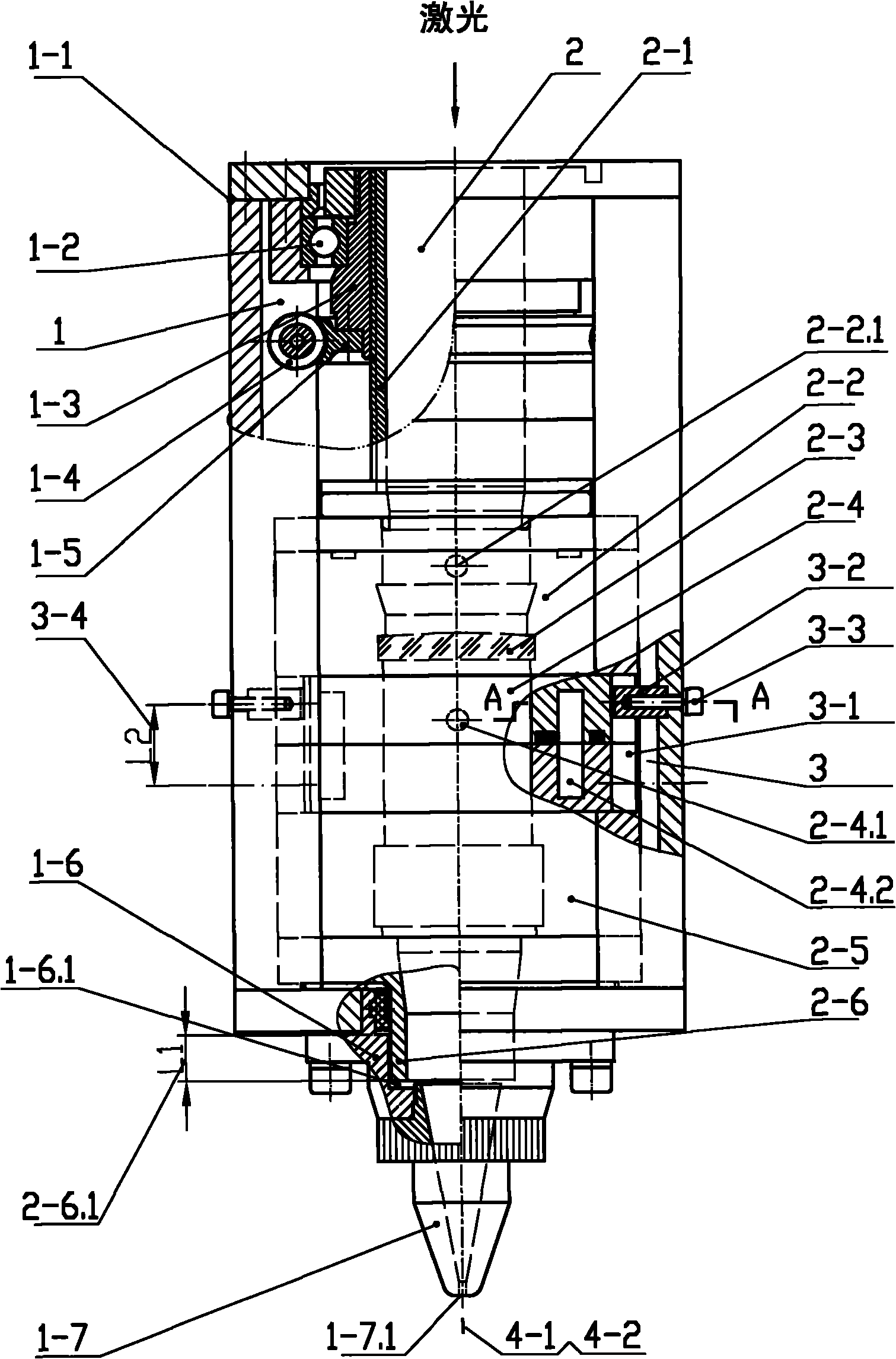
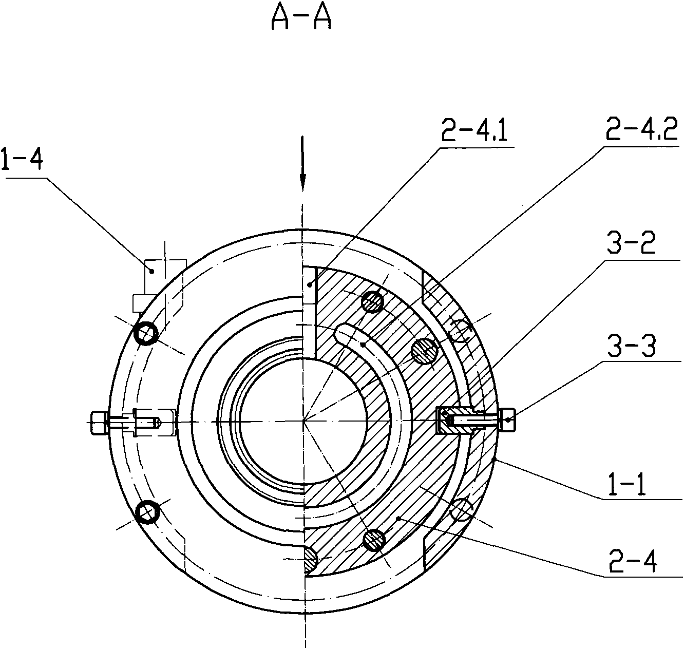
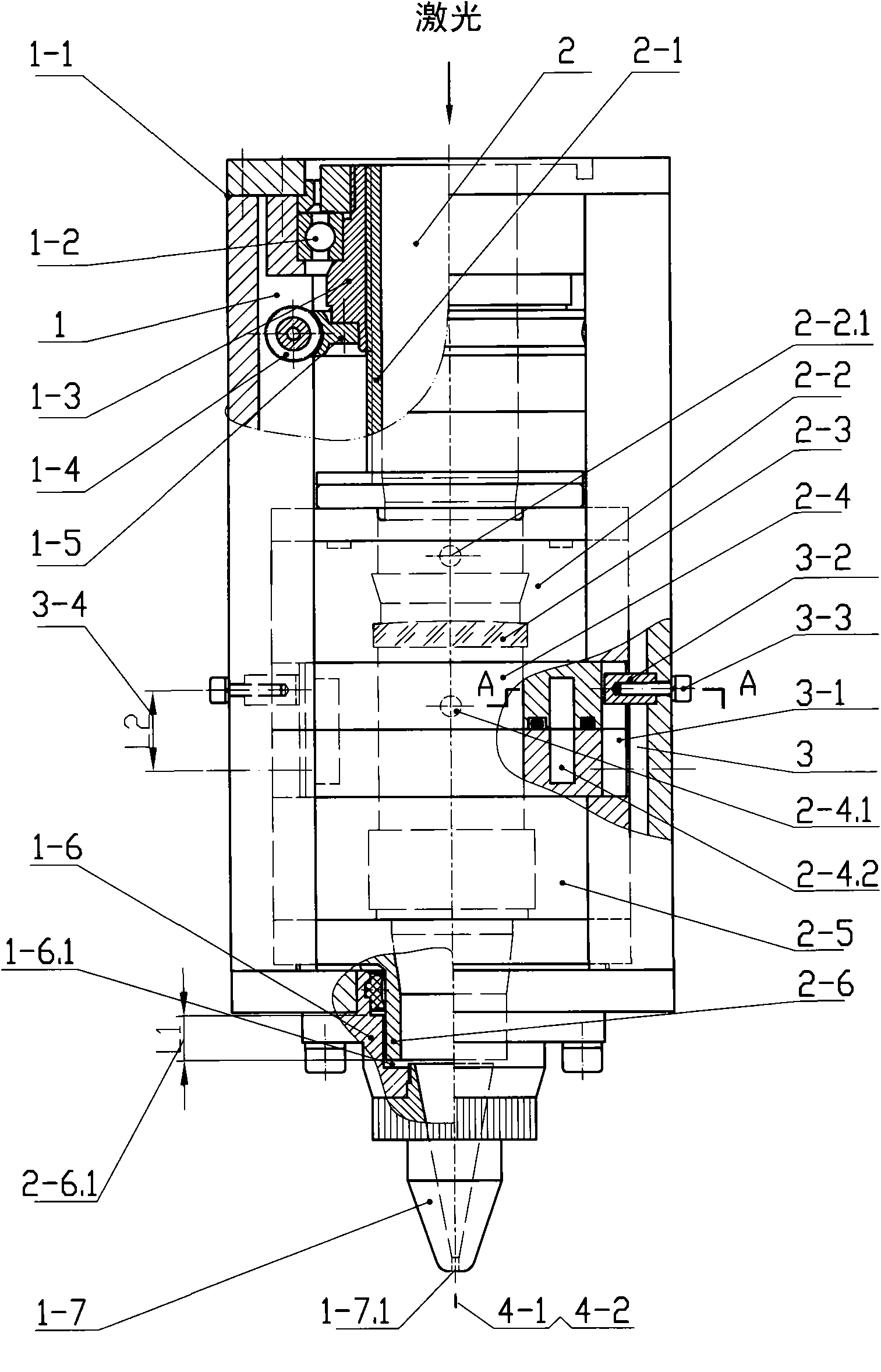
[0014] Such as figure 1 As shown, the automatic focusing CNC laser cutter of the present invention includes a frame mechanism 1, a focusing mechanism 2, a mirror seat mechanism, and a guiding mechanism 3 composed of a guiding groove 3-1, a guiding key 3-2, and a locking screw 3-3. ; The frame mechanism 1 includes a fixed sleeve 1-1, a connecting seat 1-6 and a nozzle 1-7; -3 and a trapezoidal threaded sleeve 2-1; the mirror base mechanism includes an upper mirror base 2-2, a focusing lens 2-3, a water air base 2-4, a lower mirror base 2-5 and a ventilation base 2-6, The upper mirror base 2-2 is provided with air blowing holes 2-2.1 and air blowing grooves, and the water air base 2-4 is composed of upper and lower parts. The parts are positioned by positioning pins and connected by screws; the lower end of the trapezoidal threaded sleeve 2-1 is connected with the upper lens base 2-2 through the transition flange; the guide mechanism 3 is set in the water air base 2-4 and cente...


PUM


Abstract

The invention discloses an automatic focus numerical control laser cutter, which comprises a framework mechanism (1), a focusing mechanism (2), a lens seat mechanism and guide mechanisms (3) consisting of guide slots (3-1), guide keys (3-2) and locking screws (3-3). The framework mechanism comprises a fixed sleeve (1-1), a connecting seat (1-6) and a nozzle (1-7); the focusing mechanism comprises a worm (1-4), a worm gear (1-5), a bearing (1-2), a nut (1-3) and a trapezoidal thread sleeve (2-1); the lens seat mechanism comprises an upper lens seat (2-2) of a blow hole (2-2.1), a focusing lens (2-3) and an aqueous vapor seat (2-4) which consists of an upper part and a lower part and is provided with a blow hole (2-4.1) and an annular cooling water tank (2-4.2), a lower lens seat (2-5) and a ventilation seat (2-6); and the guide mechanisms are arranged in the aqueous vapor seat and bilaterally and symmetrically distributed by taking an axis of the cutter as a center. The cutter with the structure can realize high-precision, high-efficiency and smooth automatic focusing and has large focusing range and good focusing effects so as to expand the thickness range of plates to be cut.

Description

1. Technical field [0001] The invention relates to a mechanical processing equipment, in particular to a laser cutter of a CO2 numerical control laser cutting machine. 2. Background technology [0002] CNC laser cutter is the main functional part of CNC laser cutting machine. Patent ZL200610043516.X discloses a numerically controlled laser cutting head, that is, a numerically controlled laser cutter, which consists of a connecting pipe, a mirror holder box, a water cooling assembly, a focusing mirror holder assembly, a focusing lens, a ventilation assembly, an adjusting nut, and a high-strength insulation isolation It is composed of sleeve, transition nozzle and cutting nozzle. Compared with other laser cutting machines of the same power, it has the advantages of thicker sheet material, higher sheet material utilization rate, good cooling effect of focusing lens and no thermal deformation caused by focusing, etc., but There are the following deficiencies: First, because its...

Claims


Application Information

Patent Timeline
IPC IPC(8): B23K26/38B23K26/04B23K26/046
Inventor 邱禄魁戴玉花
Owner LONGYAN LISHANG PRECISION MACHINERY
Learn More