Method for installing and locating bodywork cavity

A technology of installation positioning and cavity, which is applied in the direction of auxiliary devices, auxiliary welding equipment, welding/cutting auxiliary equipment, etc., can solve the problems affecting the accuracy and welding quality of the car body, water leakage, poor consistency, etc., to avoid the problem of self-positioning failure, Crash test is beneficial and beneficial to the effect of precision

Inactive Publication Date: 2010-09-22
CHERY AUTOMOBILE CO LTD
View PDF7 Cites 2 Cited by
  • Summary
  • Abstract
  • Description
  • Claims
  • Application Information

AI Technical Summary

Problems solved by technology

[0004] One, such as figure 1 As shown, the opening size of the rear floor cavity of the car body is 58.8mm, and the X positive direction (horizontal) positioning is not considered at the overlap of the rear floor front beam assembly of the previous weldment and the rear floor assembly of the subsequent weldment, resulting in two When mating, the consistency of the middle and rear bottom plate assembly in the positive X direction is poor, which makes the installation point on the part deviate greatly, and the relative position of the mating cannot be guaranteed, and the overlapping edge is reduced, resulting in a half point of welding, which affects the accuracy and welding quality of the body.
[0005] Two, such as figure 2 As shown, the opening size of the engine compartment cavity of the vehicle body is 33.5 mm. Considering the X-direction positioning problem, a flanging structure is designed at the lap joint for self-positioning. The front windshield beam upper cover assembly of the welded parts is relatively long (about 1322mm in length), and the material thickness is small (0.7mm), which makes the rebound of the stamping parts unavoidable, resulting in X Self-positioning in one direction fails, resulting in poor consistency in X-direction and Z-direction accuracy of related installation points, affecting the assembly of the front windshield and gutter, and there is a risk of uneven fit and water leakage

Method used


Image

  • Method for installing and locating bodywork cavity
  • Method for installing and locating bodywork cavity
  • Method for installing and locating bodywork cavity

Examples


Embodiment 1

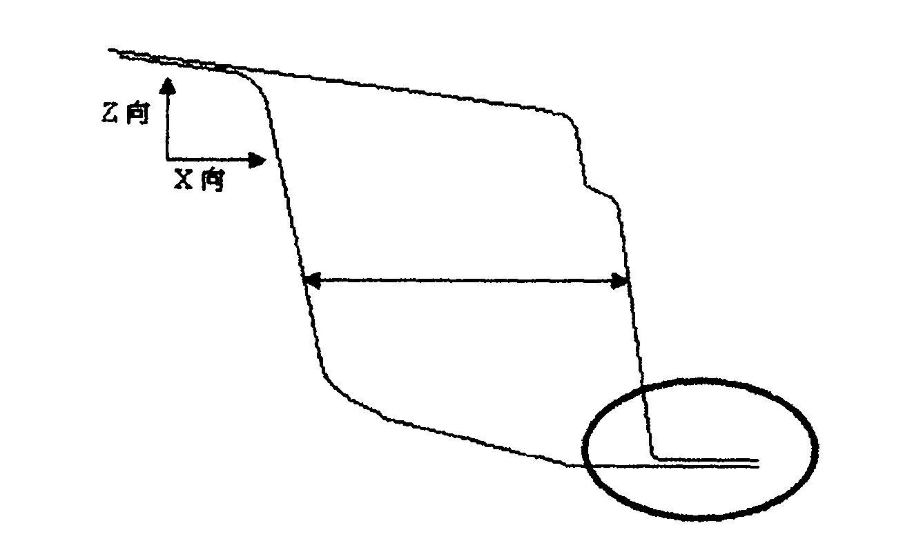
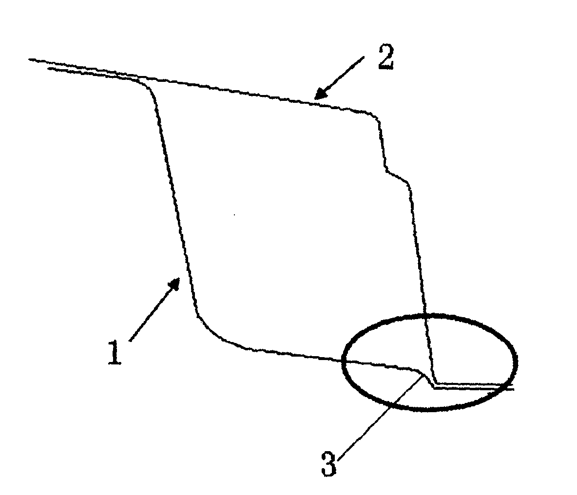
[0024] Such as image 3 As shown, the rear bottom plate 2 of the pre-sequence weldment (the first weldment in the splitting process) rear floor front beam assembly 1 and the subsequent weldment (the last weldment in the splitting process) are welded to form the rear floor cavity of the vehicle body. The rear end of the front beam assembly 1 of the rear floor is provided with a boss 3, the height of the boss is 8-12mm, and the preferred height is 10mm. The middle and rear bottom plate 2 moves in the X direction to ensure the consistency of the two parts.

Embodiment 2

[0026] Such as Figure 4 As shown in the figure, the welded components of the front windshield beam rear end plate assembly 4 and the subsequent welded piece (the welded piece after the disassembly process) front windshield beam upper cover assembly 5 are welded together. Body rear floor cavity. The rear end of the front beam assembly 1 of the rear floor is provided with a boss 6, the height of the boss is 8-12mm, and the preferred height is 10mm. ) to regulate the positioning, to prevent the front windshield beam upper cover plate assembly 5 from shifting in the X direction, and to ensure the consistency of the two pieces.


PUM


Abstract

The invention relates to a method for installing and locating a bodywork cavity, aiming at effectively solving the problem of location when the bodywork cavity is installed. The method has the technical scheme that the tail end of a preposed welding part of the bodywork cavity is provided with a boss, and the boss is used for transverse location when a post-positioned welding part of the bodywork cavity is welded with the preposed welding part.

Description

technical field [0001] The invention relates to a method for installing and positioning a vehicle body cavity. Background technique [0002] In the early design process of the car body, in order to enhance the stiffness and deflection of a certain part, prevent the structural deformation of this area and affect the performance of the whole vehicle, it will be designed as a cavity structure to meet the strength and collision requirements of the car body. However, considering the overall vehicle shape design and the space constraints of the assembly parts, the opening size of the cavity structure is often small, generally between 30mm-70mm, which makes it impossible to add a clamp positioning mechanism for positioning in the cavity. [0003] In the prior art, there are mainly two ways to install the body cavity: [0004] One, such as figure 1 As shown, the opening size of the rear floor cavity of the car body is 58.8mm, and the X positive direction (horizontal) positioning i...

Claims


Application Information

Patent Timeline
Patent Type & Authority Applications(China)
IPC IPC(8): B23K37/04
Inventor 储昭地任立芳
Owner CHERY AUTOMOBILE CO LTD
Why Eureka
Try Eureka