
Two-stage cadence braking master valve (type V)

A brake master valve and point brake technology, which is applied in the direction of brakes, brake components, control valves and air release valves, can solve the problems of affecting the braking effect, weak braking force and unsafety

Inactive Publication Date: 2010-09-22
CHANGTONG TECH
View PDF0 Cites 72 Cited by
  • Summary
  • Abstract
  • Description
  • Claims
  • Application Information

AI Technical Summary

Problems solved by technology

[0002]The existing standard brake master valve has weak braking force and cannot control the braking distance well under heavy load; there is also heavy rebound force of the control pedal, This shortcoming directly affects the operating comfort, and will increase the driver's physical exertion and other shortcomings.
[0003] In order to improve the above shortcomings, people have invented a "light load powerful master cylinder", this technology can obviously improve the above shortcomings, but it also has many problems Defects, the principle of this technology is that under the same conditions after changing the airflow speed and airflow speed up, it is easier to damage the brake system accessories, such as brake pads, brake drums, pipe fittings, etc., and seriously affect the suspension system. In addition, under the same conditions If the brake is too fast, the foot feel is not easy to control, and it is easy to cause the brake pad to heat up rapidly, resulting in carbonization, which directly affects the braking effect. If the brake is too fast, it will also cause slippage and affect the overall stability, resulting in unsafety , or unnecessary economic loss

Method used


Image

  • Two-stage cadence braking master valve (type V)
  • Two-stage cadence braking master valve (type V)
  • Two-stage cadence braking master valve (type V)

Examples


Embodiment

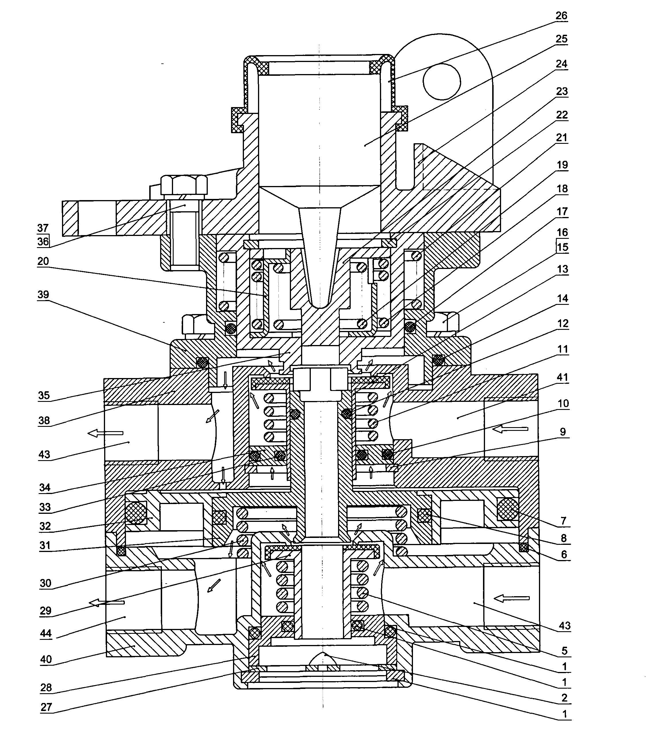
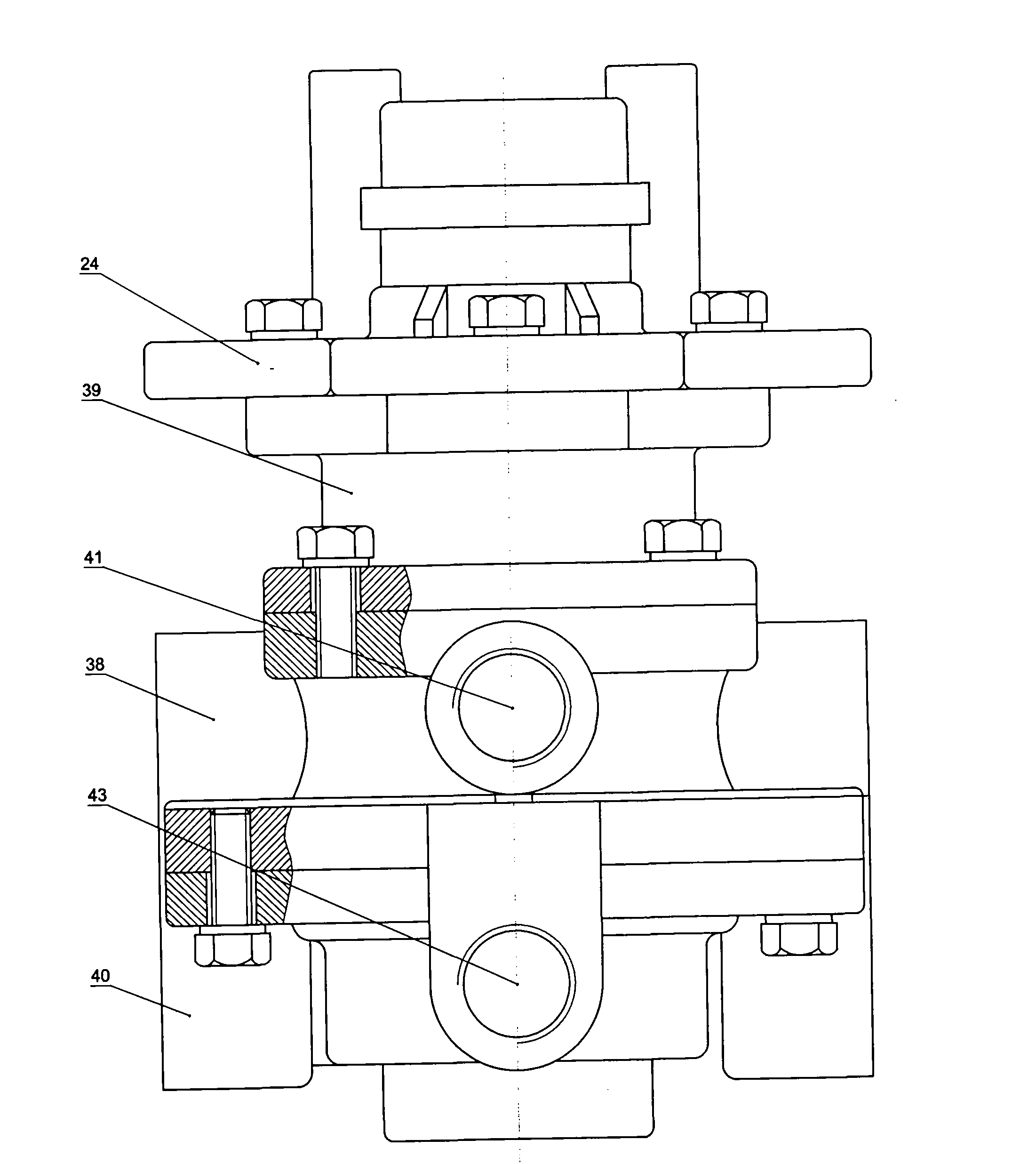
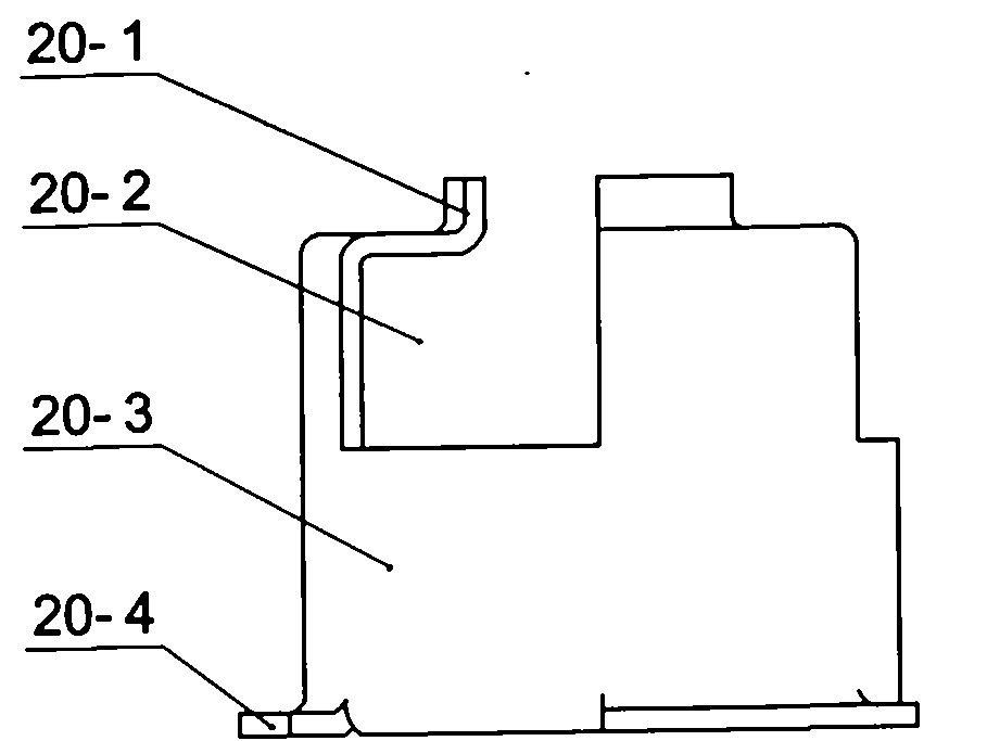
[0027] Embodiment: a two-stage point brake master valve (V type), including an upper valve body 24, a middle valve body 38 and a lower valve body 40, and a piston cylinder 39 is passed between the upper valve body 24 and the middle valve body 38 The connection is sealed and fixed, the upper edge of the lower valve body 40 and the lower edge of the middle valve body 38 are matched and nested and sealed and fixed, and the upper piston assembly and the lower piston assembly are respectively sleeved in the piston cylinder 39 and the middle valve body 38, An annular piston sleeve 32 is sleeved between the middle valve body 38 and the lower valve body 40, and an upper valve assembly and a lower valve assembly are respectively arranged in the piston sleeve 32 and the lower valve body 40; the sides of the middle valve body 38 are respectively An air inlet 41 and three air outlets 43 (two by two perpendicular to each other) are provided, and the side of the lower valve body 40 is respec...


PUM


Abstract

The invention relates to a two-stage cadence braking master valve (type V), which comprises an upper valve body, a middle valve body and a lower valve body, wherein the upper valve body and the middle valve body are connected, sealed and fixed by a piston cylinder body; the upper edge of the lower valve body and the lower edge of the middle valve body are matched, nested, sealed and fixed; an upper piston assembly and a lower piston assembly are respectively arranged in the piston cylinder body and the middle valve body; an upper valve assembly and a lower valve assembly are respectively arranged in the middle valve body and the lower valve body; an inlet hole and an outlet hole are respectively arranged on the side surfaces of the middle valve body and the lower valve body; and the upperpiston assembly comprises an upper piston, a spring kit clamp and a mandril base. The braking master valve can generate sudden energy in the weak pressure phase at the beginning of braking, can promote rapid and powerful combination between a brake pad and a friction sheave to always maintain in a good combination condition and ensure a favorable braking effect. Meanwhile, the friction between the brake pad and the friction sheave can be reduced to the minimum extent, the brake pad is prevented from carbonizing and the service life of a braking system is prolonged.

Description

1. Technical field [0001] The invention relates to an automobile brake master valve, in particular to a two-stage point brake master brake valve (V type). 2. Background technology [0002] The existing standard brake master valve has weak braking force and cannot control the braking distance well under heavy load; there is also heavy rebound force of the control pedal, which directly affects the operating comfort and increases the driver's Disadvantages such as physical exertion. [0003] In order to improve the above shortcomings, people invented a "light-load powerful master cylinder". This technology has significantly improved the above shortcomings, but it also has many defects. Under the same conditions, it is easier to damage the accessories of the braking system, such as brake pads, brake drums, pipe fittings, etc., which will affect the suspension system. The plate heats up rapidly, resulting in carbonization, which directly affects the braking effect. If the brake...

Claims


Application Information

Patent Timeline
IPC IPC(8): B60T15/06
Inventor 田青锋
Owner CHANGTONG TECH
Learn More