Method for processing blast furnace liquid slag and recycling energy and application thereof

An energy recovery and liquid slag technology, which is applied in recycling technology, seawater treatment, heating water/sewage treatment, etc., can solve the problems of high water consumption in blast furnace slag treatment system, and the inability to recycle the heat of blast furnace liquid slag for recycling rate, etc. The effect of achieving significant utilization value and improving cooling speed

Active Publication Date: 2010-09-22
SHANDONG PROVINCE METALLURGICAL ENG CO LTD
View PDF0 Cites 16 Cited by
  • Summary
  • Abstract
  • Description
  • Claims
  • Application Information

AI Technical Summary

Problems solved by technology

[0015] The technical problems to be solved in the present invention include: 1. To solve the problem of high water consumption in the blast furnace slag treatment system, reduce the water consumption per ton of slag treated by bla

Method used


Image

  • Method for processing blast furnace liquid slag and recycling energy and application thereof
  • Method for processing blast furnace liquid slag and recycling energy and application thereof
  • Method for processing blast furnace liquid slag and recycling energy and application thereof

Examples


Embodiment 1

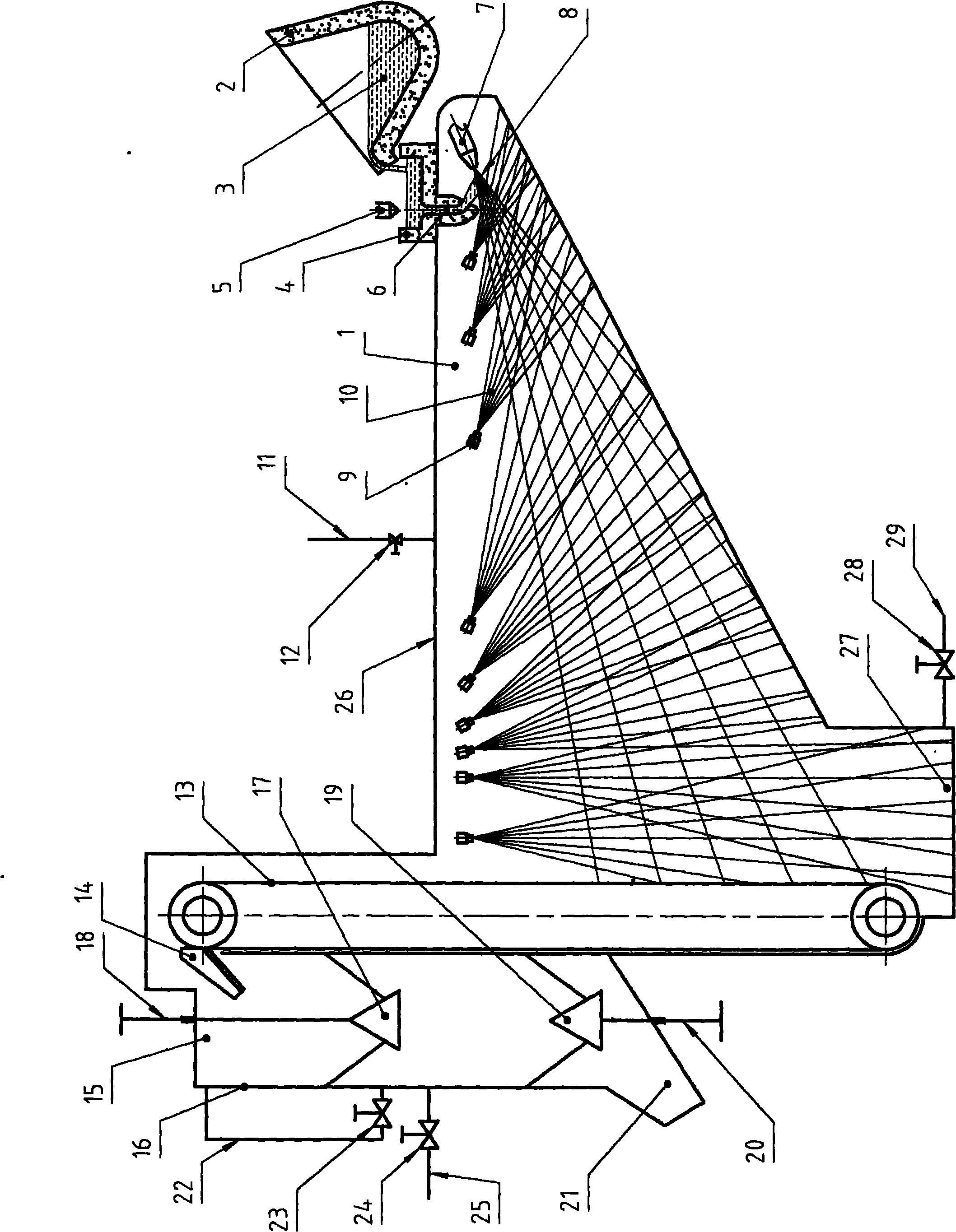
[0059] Example 1, such as figure 1 shown.

[0060] exist figure 1 Among them, 1 is the closed space, 2 is the slag tank, 3 is the slag liquid in the slag tank, 4 is the middle slag tank, 5 is the slag liquid control stopper of the middle slag tank 4, and 6 is the channel for the slag liquid to enter the closed space 1 , 7 is the nozzle of fluid water, 8 is the flow of fluid water ejected by the nozzle 7 of fluid water, 9 is the nozzle arranged in the closed space 1, 10 is the cooling water flow ejected from nozzle 9, and 11 is steam recovery Pipe, 12 is an on-off valve, 13 is a solid material hoist, 14 is a discharge chute of the hoist 13, 15 is a double material bell type discharge bin, 16 is a shell of the discharge bin 15, and 17 is a discharge bin 15 is the feeding bell, 18 is the control guide rod of the feeding bell, 19 is the unloading bell of the discharge bin 15, 20 is the control guide rod of the unloading bell 19, 21 is the discharge chute of the unloading bin 1...

Embodiment 2

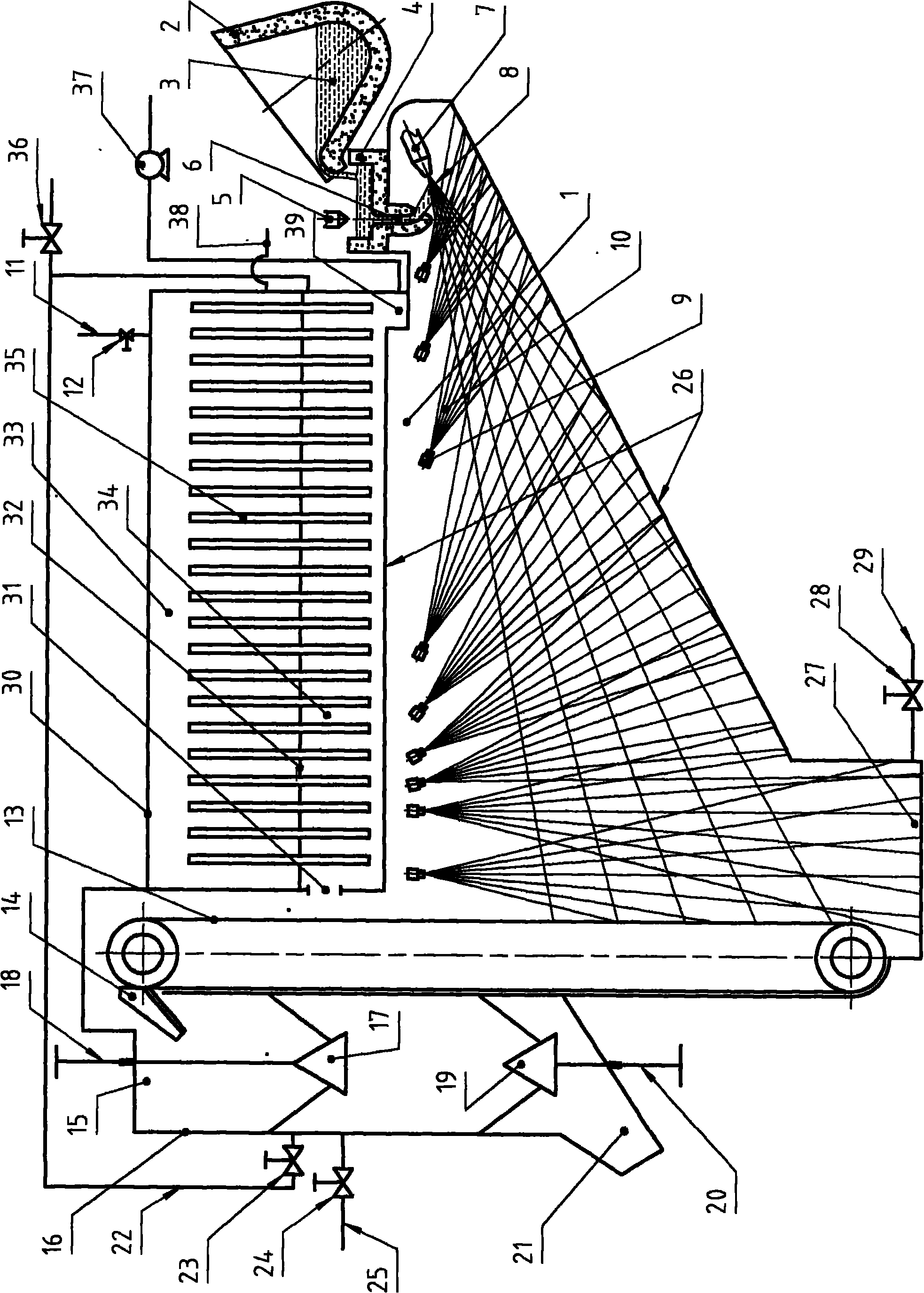
[0079] Example 2, such as figure 2 shown.

[0080] This embodiment only adopts an intermediate heat exchanger on the basis of embodiment 1 to isolate the steam containing dust and water mist.

[0081] exist figure 2 Among them, 30 is an intermediate heat exchanger, 31 is the entrance of the steam from the closed space 1 entering the intermediate heat exchanger 30, 32 is an intermediate partition that separates the intermediate heat exchanger 30 into an evaporation chamber 33 and a condensation chamber 34, and 35 is A heat pipe for heat exchange, 36 is a release valve, 37 is a hot water pump, 38 is a clean water inlet pipe, and 39 is a condensed water sump. Please refer to the relevant description of Embodiment 1 for the rest.

[0082] In this embodiment, the steam from the closed space 1 enters the condensation chamber 34 of the intermediate heat exchanger 30 through the inlet 31, and uses the heat pipe 35 to perform heat exchange, and the condensed water generated during...

Embodiment 3

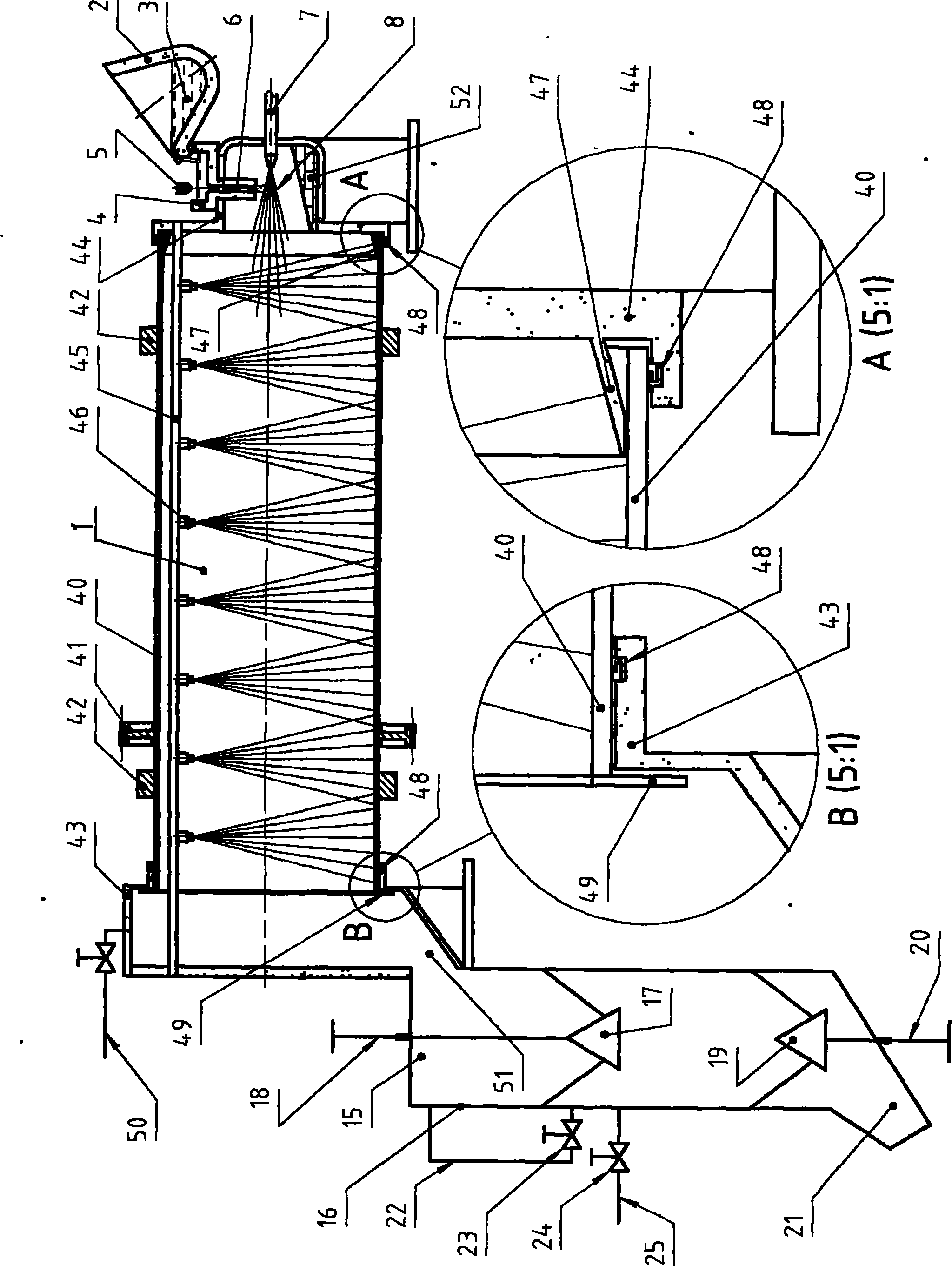
[0087] Example 3, such as image 3 shown.

[0088] This embodiment is an improvement on the basis of Embodiment 1 and Embodiment 2. The main improvement point is that: the closed space includes the space formed by the inner volume of the drum, and the complete solidification of the liquid slag, calculated by weight percentage, at least 10% is finally completed in this space.

[0089] exist image 3 Among them, 40 is the drum, 41 is the driving gear of the drum 40, 42 is the rolling ring of the drum 40, as for the supporting wheel and the rotary driving device of the drum 40, etc., they are not shown in the figure, 43 is the discharge end seat, 44 45 is a fixed beam erected on the inside of the drum 40, and facilities such as nozzle 46 (actually a nozzle group), detection probes, etc. are installed on the beam, and 47 is a protective plate at the blowing end, which can be Fixed on the blowing end seat 44, 48 is a seal, which can be a variety of finished parts with standard s...


PUM


Abstract

The invention discloses a method for processing blast furnace liquid slag and recycling energy and application thereof. The method comprises the steps of setting a pipe network, setting a control device and the like, and is characterized in that a confined space is set; the blast furnace liquid slag is led into the confined space; in the confined space, the blast furnace liquid slag entered in the confined space is granulated and then is solidified by using flowing water; the slag discharging temperature of the solidified solid slag is not higher than the boiling point of the water in the confined space; and the generated solid slag is discharged from the confined space; the generated flowing water is collected from the confined space and put to use. The invention is mainly used for solving the problems of high water consumption of a blast furnace slag processing system, unavailable recycling and/or low recycling rate of heat contained in the blast furnace liquid slag of the traditional slag processing system, recycled energy quality required to be improved and the like. Besides the application to the technical fields of blast furnace liquid slag processing and energy recycling, the invention can be also applied to the technical field of sea water desalination and the like.

Description

technical field [0001] The invention relates to a treatment and energy recovery method of blast furnace liquid slag and its application. Background technique [0002] While producing molten iron, the blast furnace also produces a large amount of liquid slag. Blast furnace liquid slag contains high heat energy. Including the heat of fusion and physical sensible heat, the heat contained in each ton of blast furnace liquid slag is close to the heat contained in 100kg of standard coal. [0003] At present, hydraulic slag flushing in front of the blast furnace is the preferred method for slag treatment. There are usually four methods of hydraulic slag flushing: sedimentation tank sedimentation method, Lhasa method, Yinba method and wheel method slag granulation device. The common feature of these methods is that the temperature of the cooling water is required to be lower than 70°C, otherwise, a large amount of foamy slag will be generated, which will affect the quality of the ...

Claims


Application Information

Patent Timeline
IPC IPC(8): C21B3/06C21B3/08C02F1/04C02F103/08
CPCC21B2400/024C21B2400/062C21B2400/08Y02A20/124Y02P10/20Y02W30/50
Inventor 钱纲姚朝胜王子金魏新民谷卓奇于国华钱舵
Owner SHANDONG PROVINCE METALLURGICAL ENG CO LTD
Why Eureka
Try Eureka