Supercharge Your Innovation With Domain-Expert AI Agents!

Membrane valve carbon canister

A diaphragm valve and carbon canister technology, applied in the direction of diaphragm valves, diaphragms, valve devices, etc., can solve the problems of low selectivity of engine operating conditions, reduced reliability, and spring force that cannot be too large, so that it is not easy to operate errors , Simple structure and reliable effect

Active Publication Date: 2013-04-24
ZHEJIANG FAI ELECTRONICS
View PDF1 Cites 0 Cited by
  • Summary
  • Abstract
  • Description
  • Claims
  • Application Information

AI Technical Summary

Problems solved by technology

In addition, the spring force used in the diaphragm valve in the above scheme should not be too large, and there are strict requirements on the hardness of the diaphragm. The strength of the diaphragm can be selected to be relatively low, otherwise the reliability of the diaphragm valve closing will be reduced. Attached engine operating condition selectivity is small

Method used


Image

  • Membrane valve carbon canister
  • Membrane valve carbon canister
  • Membrane valve carbon canister

Examples


Embodiment 1

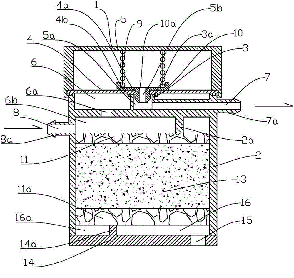
[0021] As shown in the figure, it is a cross-sectional view of the first embodiment provided by the present invention. Diaphragm valve canister main components include: upper body 1, lower body 2, valve seat 3, diaphragm 4. The diaphragm 4 and the valve seat 3 separate the space formed by the upper body 1 and the lower body 2 into a vacuum chamber and an oil-gas chamber 6 . The upper body 1 and the lower body 2 are usually made of plastic and other materials, and they can be connected by means of elastic fastening, screws, welding, etc.

[0022] The vacuum chamber includes a first vacuum chamber 5 and a second vacuum chamber 5a, the second vacuum chamber 5a is in communication with the desorption channel 7, and the lower body includes a desorption nozzle 7a surrounding the desorption channel 7.

[0023] The diaphragm 4 includes a spring seat 10, the spring seat 10 includes a protrusion 10a for positioning between the diaphragm 4, the protrusion 10a can be a rotating body with...

Embodiment 2

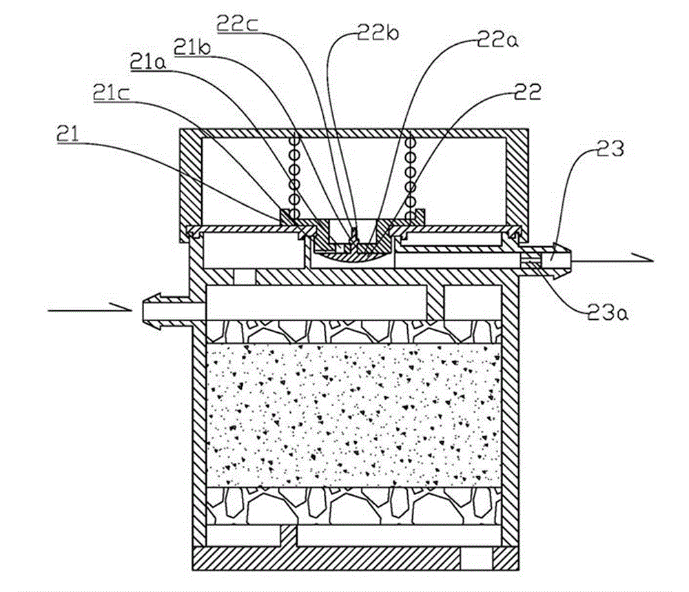
[0031] Such as figure 2 A cross-sectional view of the second embodiment provided by the present invention is shown. Parts not particularly marked are the same as in Example 1, and repeated parts have the same labels. The main difference with Embodiment 1 is that this embodiment is provided with a check valve between the first vacuum chamber 5 and the second vacuum chamber 5a. Such as figure 2 As shown, this one-way valve is a common umbrella valve, including an umbrella valve body 22 and a valve seat 21, the umbrella valve body 22 is provided with a valve stem 22c and a spherical protrusion 22b, and the valve seat 21 includes a central hole 21b and a surrounding The flow hole 21a arranged in it, the spherical protrusion 22b passes through the middle hole 21b to reach the other side of the valve seat 21 through elastic deformation, and then provides sealing elastic force for the umbrella valve, so that the umbrella valve body 22 covers the flow hole 21a, thereby preventing ...


PUM


Abstract

The invention provides a membrane valve carbon canister, and belongs to the technical field of emission control of harmful gas in fuel machinery. The desorption of the carbon canister is controlled by the vacuum degree; the carbon canister comprises an upper body and a lower body, wherein the lower body comprises a valve seat, a space between the upper body and the lower body is divided into a vacuum room and an oil-gas room by a membrane and the valve seat; and the carbon canister is characterized in that: the vacuum room comprises a first vacuum room and a second vacuum room, wherein the first vacuum room and the second vacuum room are respectively arranged on both sides of the membrane, a desorption channel is communicated with the second vacuum room, and when the membrane is separatedfrom the valve seat, fuel in the oil-gas room enters the second vacuum room and is desorbed from the desorption channel. The carbon canister has the advantages of simple and reliable structure, long service life and difficult occurrence of misoperation.

Description

technical field [0001] The invention belongs to the technical field of harmful gas emission control of fuel machinery, and relates to motor vehicles such as automobiles and motorcycles, general fuel power devices such as gasoline generators and lawn mowers, and in particular to an active diaphragm valve carbon tank for absorbing fuel vapor. Background technique [0002] As an important part of fuel-fueled motor vehicles, the carbon canister is to temporarily absorb the fuel evaporated from the fuel tank in the activated carbon, and then desorbed by the intake air of the engine, and enters the combustion chamber of the engine to be burned, thereby preventing or reducing fuel consumption. Volatile into the atmosphere and waste and cause pollution to the atmospheric environment. The leakage of the carbon canister and its pipeline will not only cause fuel to be discharged into the atmosphere and cause pollution, but more importantly, it will affect the normal operation of the en...

Claims


Application Information

Patent Timeline
Patent Type & Authority Patents(China)
IPC IPC(8): F02M25/08F16K7/12
Inventor 张平杨延相张建郗大光
Owner ZHEJIANG FAI ELECTRONICS
Features
  • R&D
  • Intellectual Property
  • Life Sciences
  • Materials
  • Tech Scout
  • Unparalleled Data Quality
  • Higher Quality Content
  • 60% Fewer Hallucinations
Learn More