
Movement mechanism for linear multidigit ionization chamber

A technology of motion mechanism and ionization chamber, which is applied in the direction of circuits, discharge tubes, electrical components, etc., can solve the problems of unfavorable maintenance, troublesome repair, and large space occupied by the treatment head, and achieve the effect of strong reliability and high positioning accuracy

Active Publication Date: 2010-09-22
江苏海明医疗器械有限公司
View PDF4 Cites 2 Cited by
  • Summary
  • Abstract
  • Description
  • Claims
  • Application Information

AI Technical Summary

Problems solved by technology

[0005] The positioning of the existing ionization chamber adopts the locking method of the turntable. There are several stations around the axis of the turntable on the turntable, one of which is used as the through hole of the optical field, and the rotation of the turntable makes the center of the through hole of the optical field coincide with the center of the beam current. The position is used to optically simulate the radiation field formed by the radiation source; the other stations install the ionization chamber, and the turntable rotates to make the center of the required ionization chamber coincide with the center of the beam for dose monitoring; this kind of turntable is clamped The unique positioning method is not conducive to maintenance, especially when the rotating shaft fails, the repair is particularly troublesome
In addition, the turntable clamping ion chamber mechanism occupies a large space in the treatment head, which increases the height of the treatment head

Method used


Image

  • Movement mechanism for linear multidigit ionization chamber
  • Movement mechanism for linear multidigit ionization chamber
  • Movement mechanism for linear multidigit ionization chamber

Examples


Embodiment Construction

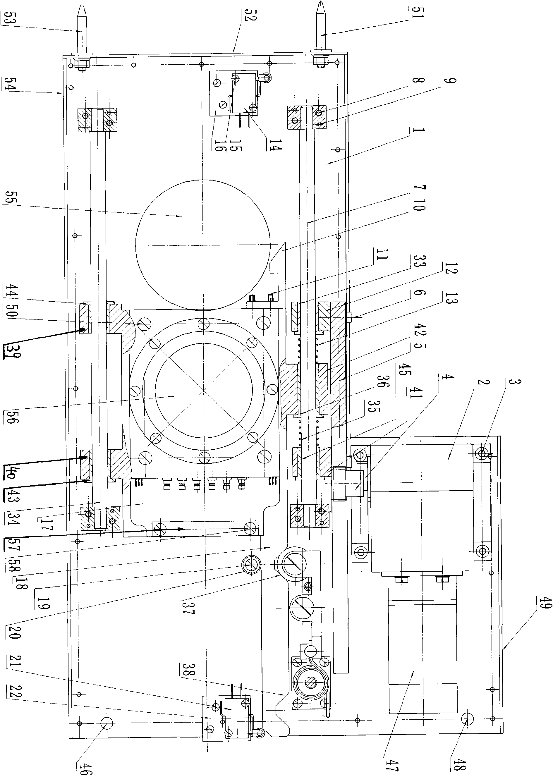
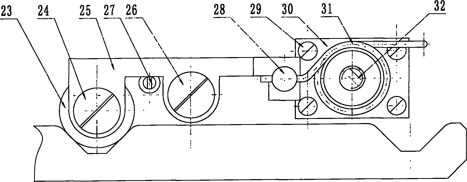
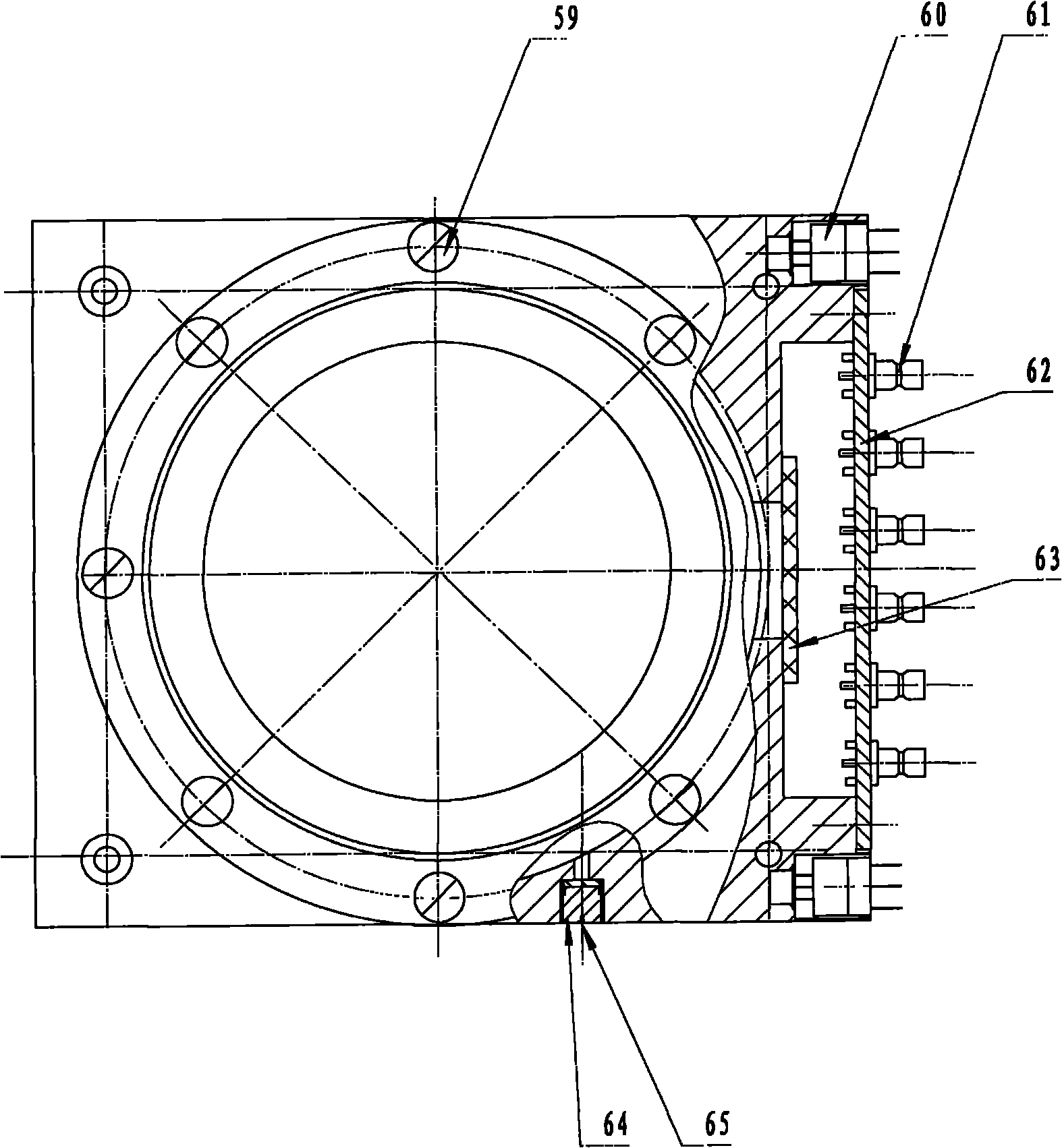
[0033] The specific implementation manner of the present invention will be described below in conjunction with the technical scheme and accompanying drawings. An example is attached figure 1As shown, a linear multi-position ionization chamber movement mechanism in the present embodiment includes a base plate (1), a driving device (2), a transmission gear (4), a transmission rack (5), a guide shaft 1 (7), a guide Shaft II (34), load frame (17), micro switch I (21) and micro switch II (14), compression spring I (13), compression spring II (35), connection block I (12), connection Block II (41), connecting block III (42), connecting block IV (39), connecting block V (40), sliding copper sleeve I (33), sliding copper sleeve II (45), sliding copper sleeve III (36) , sliding copper sleeve IV (44), sliding copper sleeve V (43), stop pin (19), limit lever combination.

[0034] The limit lever combination includes: positioning bearing (23), universal swivel head (28), intermediate pi...


PUM


Abstract

The technical scheme provides a modular and dismountable movement mechanism for a linear multidigit ionization chamber, which comprises a guide shaft fixed on a bottom board, a limit lever assembly, a microswitch, a load frame capable of making linear displacement with a transmission rack, a limit lever, a pressure spring, the ionization chamber arranged on the load frame and the like. The limit lever assembly comprises a positioning bearing, a universal rotating head, a torsional spring, a torsional spring connecting rod and the like; and a limit slot is formed on the limit lever fixed on the load frame. When the positioning bearing just moves to a slope of the limit slot and does not stop in the limit slot, the microswitch corresponding to the limit slot is pressed, a motor stops operating, and the torsional spring and the pressure spring push the load frame with the ionization chamber together to continue to move, so that finally the positioning bearing slides into the limit slot completely, the load frame stops moving, and a station is adjusted in place. The mechanism is arranged below a turnplate of a beam flattening filter of an accelerator to measure the intensity of radiation passing through the flattening filter, and is convenient to overhaul.

Description

field of invention [0001] The invention relates to an ionization chamber movement mechanism, in particular to a mechanically positioned linear multi-position ionization chamber movement mechanism, which belongs to the field of medical accelerators. Background technique [0002] A dose monitoring system generally consists of several ionization chambers and related electronic circuits. The main component of the dosimetry instrument used for metering delivery is also an ionization chamber, which is a detector for detecting ionizing radiation. Radiation monitoring of accelerators generally uses ionization chambers. Most of the ionization chambers are flat plates. [0003] According to the purpose and nature of the medical accelerator, the role of the dose monitoring system is very important for both treatment and safety. Therefore, the International Electrotechnical Commission (IEC) recommends that a medical electron accelerator should have at least two independent dose monitor...

Claims


Application Information

Patent Timeline
IPC IPC(8): G01T7/00G01T1/02G01T1/185H01J47/02
Inventor 张益贵吴建兴王春波王小军张国福
Owner 江苏海明医疗器械有限公司
Learn More