
Shunting coding method for digital video monitoring system and video monitoring system

A monitoring system and video monitoring technology, applied in the information field, can solve the problems that the frame code stream cannot meet two different resolutions at the same time, and cannot match the network video frame mode well, so as to reduce the amount of information and meet the requirements of network transmission , the effect of increasing the compression ratio

Inactive Publication Date: 2010-09-22
广东中大讯通信息有限公司 +2
View PDF5 Cites 10 Cited by
  • Summary
  • Abstract
  • Description
  • Claims
  • Application Information

AI Technical Summary

Problems solved by technology

In this way, the digital video surveillance system on the server side must not only meet the requirements of high-resolution video surveillance, but also produce low-resolution video images that meet the requirements of mobile phone surveillance. However, the existing video surveillance frame code stream cannot meet both requirements. Terminals with different resolution requirements
[0004] In addition, although the current network technology has been greatly developed, the speed and stability of network transmission are still restricted by various technical and environmental factors. The existing video surveillance system cannot match the existing network video frame mode well.

Method used


Image

  • Shunting coding method for digital video monitoring system and video monitoring system
  • Shunting coding method for digital video monitoring system and video monitoring system
  • Shunting coding method for digital video monitoring system and video monitoring system

Examples


Embodiment Construction

[0039] The embodiments of the present invention will be described in detail below in conjunction with the drawings.

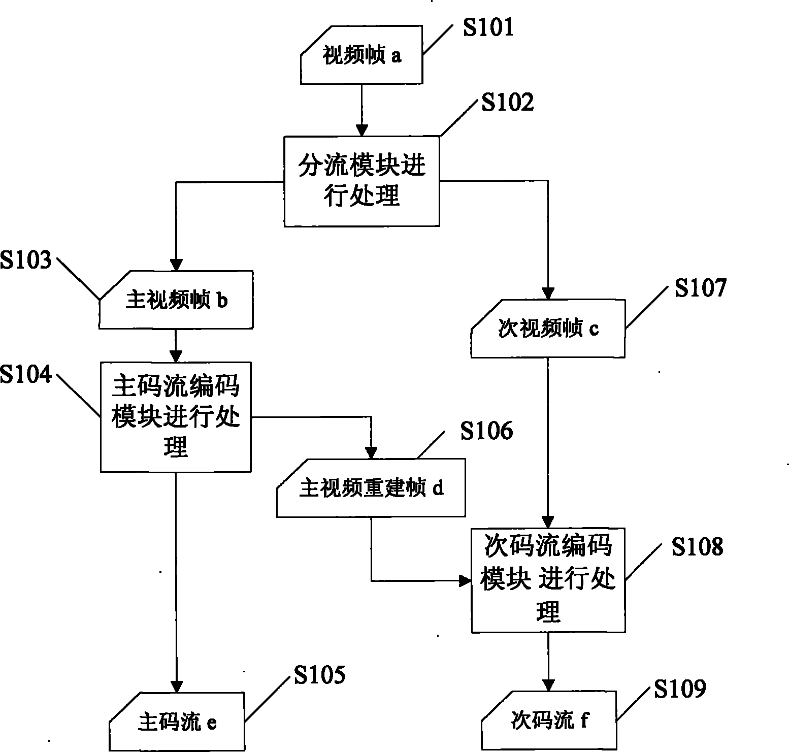
[0040] Such as figure 1 As shown, figure 1 Shows a flow chart of a streaming encoding method for a digital video surveillance system in an embodiment of the present invention, and the implementation scheme is as follows:

[0041] S101: Obtain a video frame a, that is, a video frame in a digital video surveillance system;

[0042] S102: Perform processing through the splitting module, that is, use two-dimensional wavelet transform to decompose the video frame a into primary and secondary video frames;

[0043] S103: Generate a main video frame b;

[0044] S104: The main video frame b is processed by the main stream encoding module, that is, the main video frame is encoded here to generate the main stream and the main video reconstruction frame;

[0045] S105: Generate the main stream e;

[0046] S106: Generate a main video reconstruction frame d;

[0047] S107: Generate a se...


PUM


Abstract

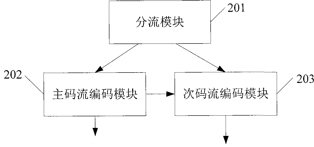
The embodiment of the invention discloses a shunting coding method for a digital video monitoring system. The method comprises the following steps: decomposing a video into primary video frames and secondary video frames by using two-dimensional wavelet transform; coding the primary video frames to generate a primary code stream and primary video reconstruction frames; and based on the primary video reconstruction frames, coding the secondary video frames to generate a secondary code stream. Corresponding, the embodiment of the invention also discloses a video monitoring system. The video monitoring system comprises a shunting module, a primary code stream coding module and a secondary code stream coding module, wherein the shunting module is used for decomposing the video into the primary video frames and the secondary video frames by using two-dimensional wavelet transform; the primary code stream coding module is used for coding the primary video frames to generate the primary code stream and the primary video reconstruction frames; and the secondary code stream coding module is used for coding the secondary video frames to generate the secondary code stream based on the primary video reconstruction frames. By implementing the invention, the digital video monitoring system can satisfy monitoring requirements for videos with different resolutions and enhance the video compression coding efficiency.

Description

Technical field [0001] The invention belongs to the field of information technology, and specifically relates to a digital video monitoring system shunt coding method and a video monitoring system. Background technique [0002] As an important security monitoring and assurance tool, video surveillance has been widely used in various industries. With the rapid development of wireless mobile network technology and mobile communication equipment technology, the demand for mobile video surveillance is increasing. [0003] Among mobile terminal devices, mobile phones dominate the mainstream due to their convenience and dexterity. While mobile phones are used in digital video surveillance, the size of the displayed video images is generally of lower resolution. In this way, the server-side digital video surveillance system must not only meet the requirements of high-resolution video surveillance, but also produce low-resolution video images that meet the needs of mobile phone surveillan...

Claims


Application Information

Patent Timeline
Patent Type & Authority Applications(China)
IPC IPC(8): H04N7/26H04N7/30H04N7/18H04N19/63
Inventor 罗笑南刘宁钟似玢吴贺丰陈健民
Owner 广东中大讯通信息有限公司
Learn More