Remote optical fiber cable temperature detection alarm system and method

A fiber optic cable and alarm system technology, applied in thermometers, thermometers with physical/chemical changes, measuring devices, etc., can solve the problems of limited popularization, short monitoring distance, and short effective service life, so as to reduce the cumbersome wiring, Positioning is convenient and accurate, and the effect of ensuring accuracy

Active Publication Date: 2014-11-12
STATE GRID SHANDONG ELECTRIC POWER +1
View PDF6 Cites 12 Cited by
  • Summary
  • Abstract
  • Description
  • Claims
  • Application Information

AI Technical Summary

Problems solved by technology

[0004] Therefore, the technical problem to be solved by the present invention is that the existing distributed optical fiber temperature measurement system based on Raman scattering has high requirements for lasers, photosensitive devices and signal processing technology, com

Method used


Image

  • Remote optical fiber cable temperature detection alarm system and method
  • Remote optical fiber cable temperature detection alarm system and method
  • Remote optical fiber cable temperature detection alarm system and method

Examples


Embodiment 1

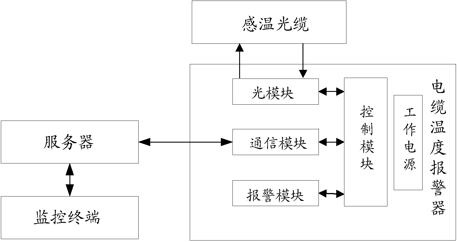
[0051] see figure 1 As shown, a remote optical fiber cable temperature detection and alarm system as an embodiment of the present invention includes: a temperature sensing optical cable, a cable temperature alarm, a server and a monitoring terminal, wherein:

[0052] A temperature-sensing optical cable, the temperature-sensing optical cable is laid together with the cable to be monitored, and each of the temperature-sensing optical cables to be monitored forms a complete optical path channel with an optical signal input end and an optical signal output end, and the temperature-sensing optical cable changes with temperature Fiber loss occurs due to the increase. The temperature-sensitive optical cable can be a special optical cable sensitive to temperature, or an ordinary optical cable with an additional temperature-sensitive physical device. bending loss. The temperature-sensing optical cable can be placed outside the monitored cable, or built into the monitored cable, that ...

Embodiment 2

[0063] As a remote optical fiber cable temperature detection and alarm system according to an embodiment of the present invention, on the basis of the above-mentioned embodiment 1, the temperature-sensing optical cable and the monitored cable are arranged in parallel and closely so that the temperature of the temperature-sensing optical cable changes It is as consistent as possible with the temperature change of the monitored cable, which ensures the accuracy of monitoring and facilitates the subsequent use of optical time domain reflectometers to locate fault points.

[0064] The temperature-sensing optical cable and the monitored cable are arranged parallel and tightly back and forth multiple times according to the requirements, and multiple temperature-sensing optical cables can be arranged in parallel on the surface of the monitored cable according to the thickness of the monitored cable and different monitoring requirements, which meets the requirements Various needs, easy...

Embodiment 3

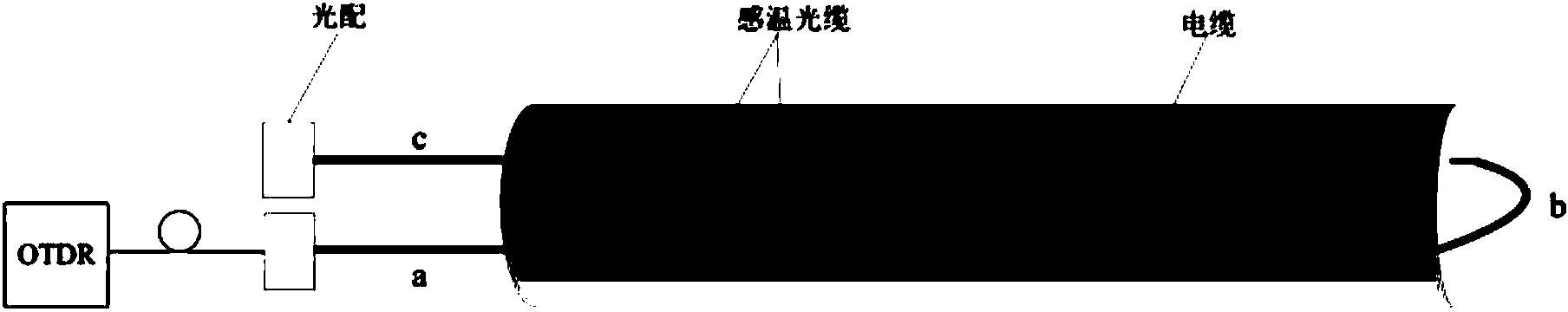
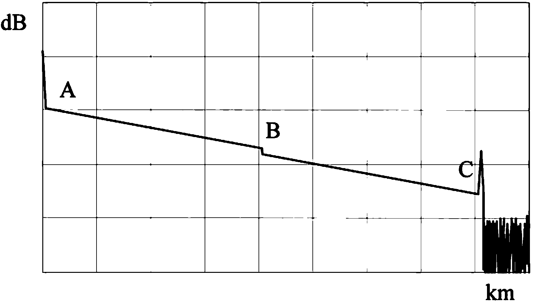
[0066] As an embodiment of the present invention, a remote optical fiber cable temperature detection and alarm system, on the basis of the above-mentioned embodiment 2, also includes an optical time domain reflectometer, which is used to determine the specific location of the fault after the fault occurs in the monitored cable . When a cable fault is detected, the fault maintenance personnel arrives at the scene with an optical time domain reflectometer, and finds out the suspected faulty cable according to the alarm signal sent by the cable temperature alarm, and sends the light of the temperature-sensing optical cable that is co-located with the suspected faulty cable. The signal input end and the optical signal output end are disconnected from the optical module of the cable temperature alarm, and the optical path is tested with an optical time domain reflectometer.

[0067] As a specific implementation, such as figure 2 As shown, it is the cable fault location OTDR test ...


PUM


Abstract

The invention provides a remote optical fiber cable temperature detection alarm system and method. If it is monitored that a cable breaks down, the temperature of a fault point rises, the attenuation of an optical signal in the transmission process in a temperature-sensing optical cable is over large, and finally the optical power of received light collected at the optical signal output end of the temperature-sensing optical cable drops abnormally and substantially; whether the monitored cable breaks down or not is judged by monitoring data of the optical power of emitted light and data of the optical power of the received light. By means of the remote optical fiber cable temperature detection alarm system and method, the technical requirement for a laser device, light-sensing signals and signal processing is low, later maintenance technology is simple, the effective life is long, the monitoring distance is long, the cost is low, and popularization and use are facilitated.

Description

technical field [0001] The invention relates to the technical field of power cable temperature measurement, in particular, the invention relates to a remote optical fiber cable temperature detection and alarm system and method. Background technique [0002] With the overall planning and construction of cities in our country, the overhead lines inside the city are gradually replaced by power cables. Power cables are basically laid by direct burial, pipe pulling or pipelines. State Grid’s 5OOKV cables are all laid in tunnels, 66KV-220KV cables are mainly laid in tunnels and pipes, and 10KV-35KV cables are mainly laid in pipes. And direct burial, which makes it difficult to visually inspect the operation of power cables, and it is also difficult to monitor and locate faults that occur during operation. Power cables are generally accompanied by local temperature rises before and during failures. Temperature is an important parameter that reflects the operation of power cables. ...

Claims


Application Information

Patent Timeline
IPC IPC(8): G01K11/32G01K11/324
Inventor 孟建黄彦周建波
Owner STATE GRID SHANDONG ELECTRIC POWER
Why Eureka
Try Eureka