Air processing device
An air treatment device and air treatment technology, applied in the direction of steam flow control, chemical instruments and methods, electrostatic effect separation, etc., can solve the problems of reduced dust collection efficiency, inability to obtain sufficient dust collection performance, and dirty walls, etc.
- Summary
- Abstract
- Description
- Claims
- Application Information
AI Technical Summary
Problems solved by technology
Method used
Image
Examples
no. 1 approach
[0100] The first embodiment of the present invention will be described.
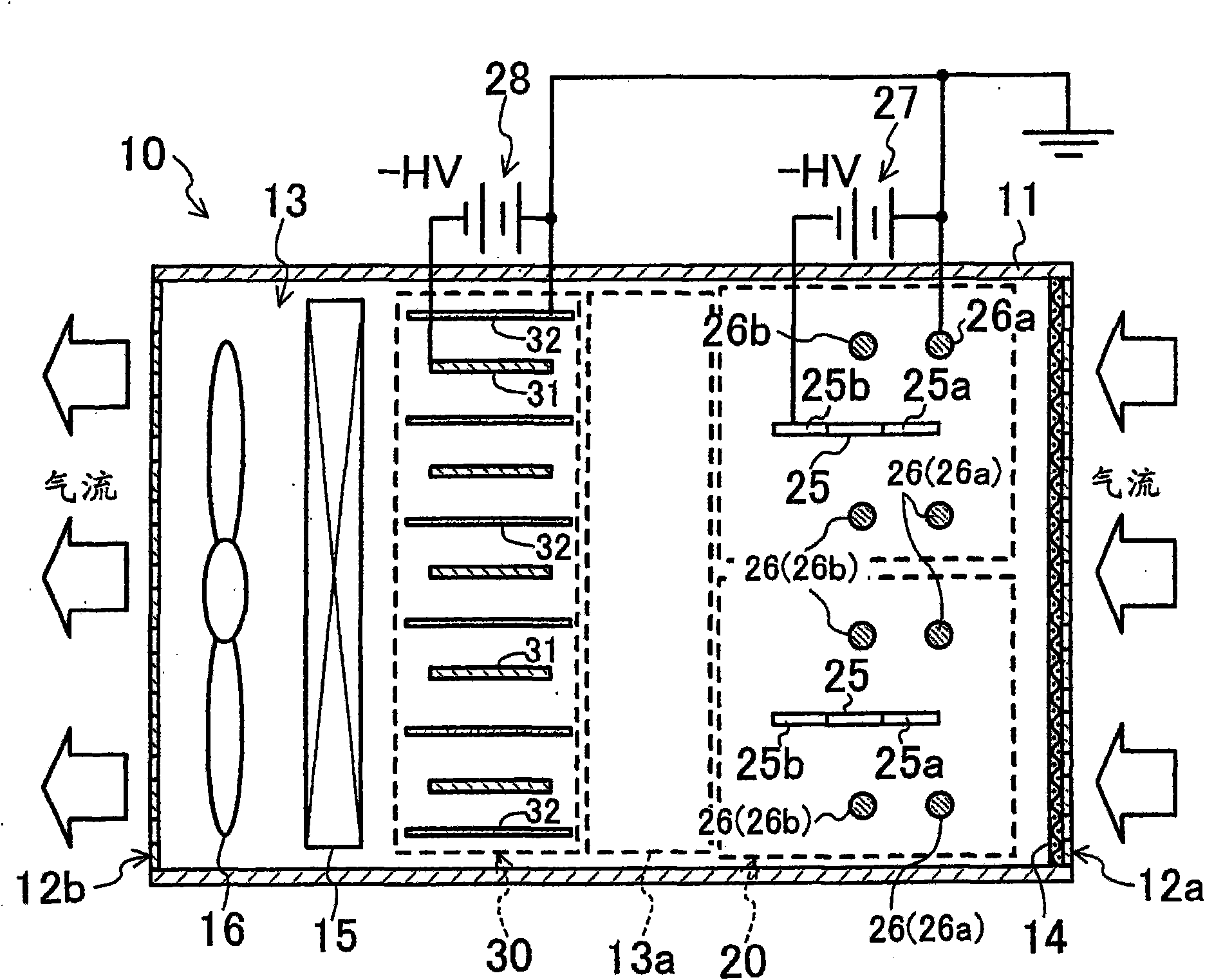
[0101] This first embodiment relates to an air cleaning device 10 as an air processing device according to the present invention. figure 1 It is a sectional view showing a schematic internal structure of the air cleaner 10 .
[0102] The air cleaning device 10 includes a rectangular parallelepiped and hollow housing 11 , and a plurality of functional components are accommodated in the housing 11 . An air suction port 12a is formed on one wall surface of the housing 11, and an air blowing port 12b is formed on a wall surface opposite to the air suction port 12a. The air suction port 12a is provided with a pre-filter 14 for capturing particles having relatively large particle diameters among dust (aerosols) contained in the air to be treated.
[0103] An air passage 13 through which air flows from the air inlet 12a to the air outlet 12b is formed in the casing 11 . In this air passage 13, a charging uni...
Deformed example 1
[0125] In the air cleaning device 10 of the first embodiment, as Figure 4 As shown, in the diffusion space 13a, a diffusion member 13b for diffusing ions into the air may also be provided.
[0126] This diffusion member 13b is composed of a filter member 13b having many fine pores. This filter member 13b has a function of diffusing ions into the air. Therefore, by providing the diffusion member 13b in the diffusion space 13a, the ion diffusion effect of this air cleaning device 10 is improved.
Deformed example 2
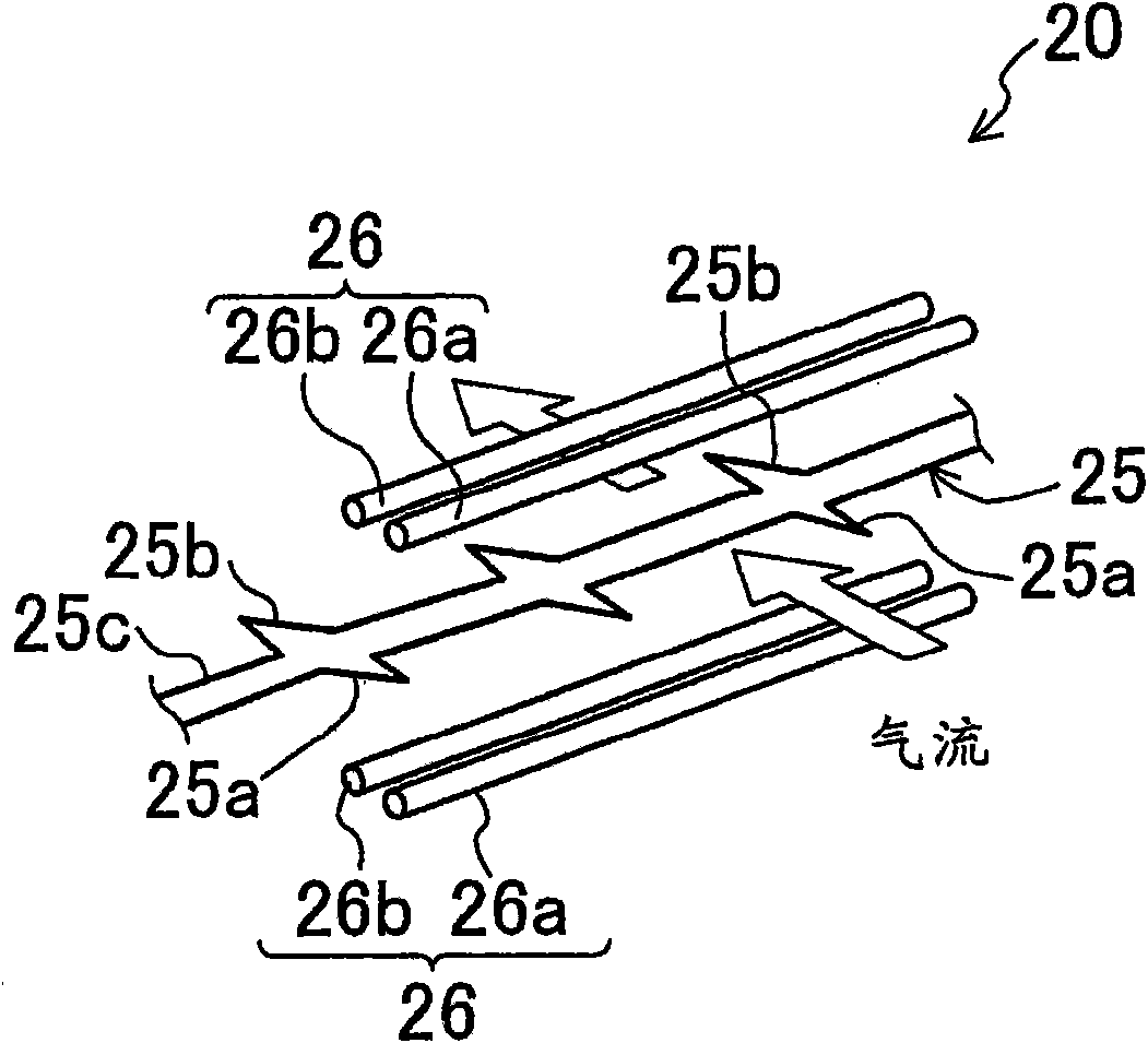
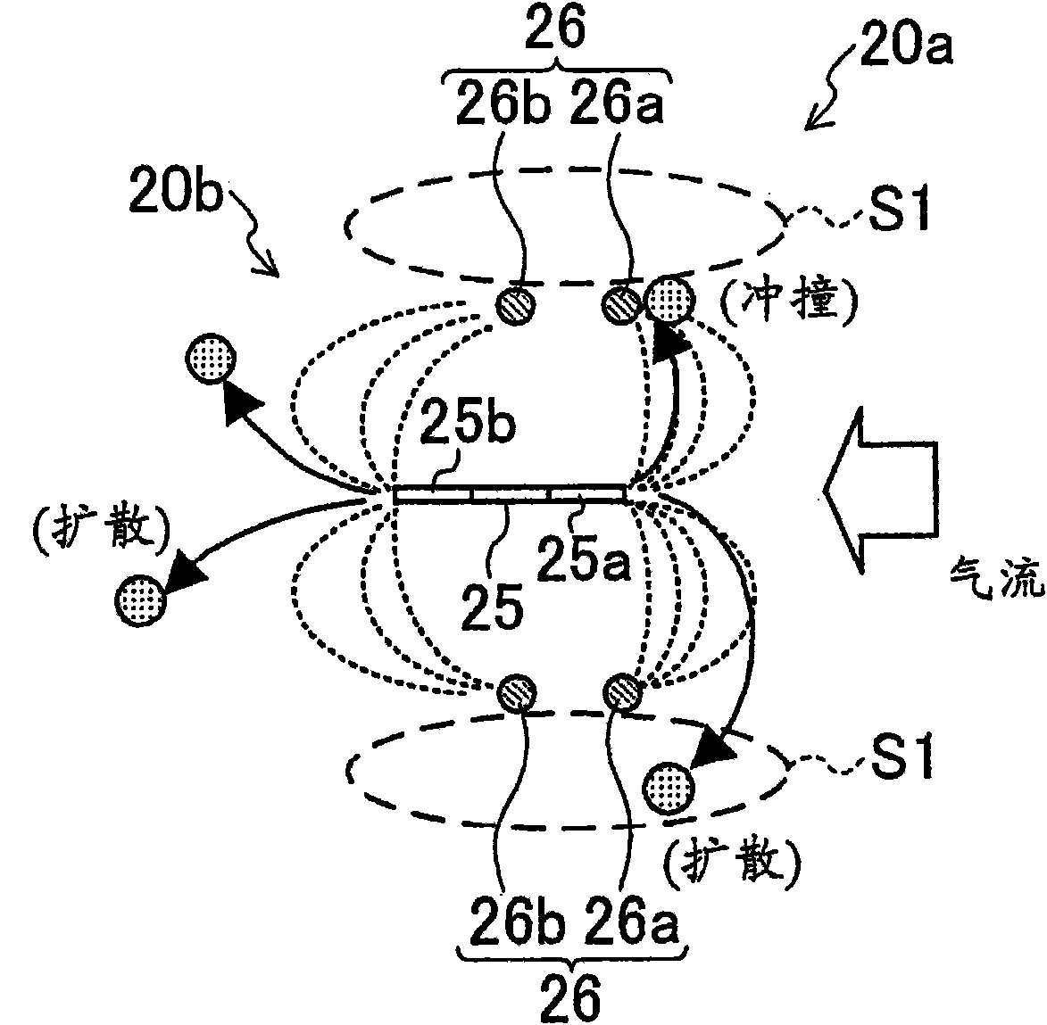
[0128] Modification 2 of the first embodiment, such as Figure 5 As shown, on the discharge electrode 25, an upstream side discharge part 25a (first discharge part 25a) having a first charging part 20a and a downstream side discharge part 25b (second discharge part 25b) having a second charging part 20b are used. In the structure of the zigzag electrode (integrated discharge electrode 25), the opposite electrode 26 of the first electrification part 20a and the opposite electrode 26 of the second electrification part 20b are also formed integrally. Specifically, the opposing electrode 26 is composed of a total of two rod-shaped electrodes arranged one above and the other between the sawtooth-shaped electrodes. The counter electrode 26 is arranged parallel to the discharge electrode 25 on a virtual vertical plane passing through the tip or almost the tip of the upstream side discharge portion 25a. In this configuration, the counter electrode 26 is arranged closer to the first d...
PUM
 Abstract
Description
Claims
Application Information
 - R&D
- Intellectual Property
- Life Sciences
- Materials
- Tech Scout
- Unparalleled Data Quality
- Higher Quality Content
- 60% Fewer Hallucinations
Browse by: Latest US Patents, China's latest patents, Technical Efficacy Thesaurus, Application Domain, Technology Topic, Popular Technical Reports.
© 2025 PatSnap. All rights reserved.Legal|Privacy policy|Modern Slavery Act Transparency Statement|Sitemap|About US| Contact US: help@patsnap.com


